An Experimental Study on Physical, Micro-mechanical, and Statistical Analysis of Chitosan - Coated on Produced 3-D Braiding Structure for Artificial ACL Grafts with EtO Sterilized
Ömer Fırat Turşucular1*![]()
1Hatin Textile, Hatin Tex Weaving Companies, Bursa, Turkey
*Correspondence to: Ömer Fırat Turşucular, MD, R&D in Chief, Hatin Textile, Hatin Tex Weaving Companies, Dosab, Bursa, 16245, Turkey; Email: omerfirattursucular@gmail.com
Abstract
Objective: It was the first study in the world on the micro-mechanical calculations, and statistical analysis of artificial ACL grafts, which were bio-composite materials.
Methods: In this study; first of all, 3-D braiding preforms (raw samples) were produced with the 3-D braiding production method, which provided high - quality biomechanical performance values with 3 different technical yarns (reinforcement elements). Afterwards, bio-composite materials were produced by using the method of impregnation with chitosan (matrix element) and auxiliary biological chemicals depending on the bio-chemical recipe. Finally, all samples were sterilized with ethylene oxide sterilization.
Results: Total volume of bio-composite materials (x10-3cm3) was T5>T3>T4>T6>T1>T2 respectively. Fiber - volume ratio of bio-composite materials (%) was T4>T6>T2>T5>T1>T3. Matrix - volume ratio of bio-composite materials (%) was T3>T1>T5>T2>T6>T4, respectively.
Conclusion: The some process parameters such as yarn type, yarn count, or braiding construction (x2 factors) were significant, and effective on the total volume, the highest fiber -volume ratio, and the highest matrix - volume ratio of artificial ACL grafts.
Keywords: biocomposite material, artificial ACL graft, 3-D braiding technology, bio-chemical finishing, EtO sterilization, physical, micro-mechanical, statistical analysis
1 INTRODUCTION
The popularity and growth of composite materials have been rapidly progressing in recent years thanks to their modulus of elasticity, toughness, lightness, and corrosion resistance in engineering and materials sciences. They have reinforcement and matrix elements. The reinforcement element is classified as fiber, particle, and lamina, and also matrix element is classified as polymer, metal, and ceramic. Bio-composites which have some unique properties like biodegradability and environmentally friendly structure in the foreground are widely used in scaffolds (as grafts in orthopedic implants) and biological packaging. They are designed with various materials and production methods according to some critical design criteria such as impact resistance, temperature resistance, tensile strength, wear strength, corrosion resistance, chemical resistance, electrical resistance, damping, and lightweight. Their production methods are hand lay - up, spray - up, filament winding, vacuum bag molding, vacuum infusion, resin transfer molding, compression molding, pultrusion, reinforced reaction injection molding, centrifugal casting, continuous lamination, gel - coated stone molding, stone surface molding, engineered stone molding, and additive manufacturing. Orthopedic applications can be produced in biomaterials. (1) When the micromechanics of composite materials are examined experimentally, there are generally thermomechanical investigations of the woven - reinforced lamina and braiding - reinforced lamina composite materials[1-15]. The stress and strain values are relative variables and a volume - based effect is studied. The coordinate system is accepted for the laminated material. Linear, orthotropic material properties and homogeneous distribution are assumed for composite materials. Independent variables are assumed for 3 different strain values, 3 different moduli of elasticity, and 3 different Poisson ratio values for 3 different axes. Mathematical inferences were made for various independent parameters and axes by forming matrices from the volume - based Equation (1) separately for the mean stress, strain, and modulus of elasticity values and making integral calculations[2-16]. The fiber - to - volume ratio (%) was found by the following mass relation.
|
Vf means the volume of the fiber. wf means the weight of the fiber (reinforcement element). ρc means the density of the composite. wc means the weight of the composite. ρf means the density of the fiber (reinforcement element). Ligaments have low regeneration. Tissue damage is frequently observed in athletes, active workers, and the elderly. Thus, pain, disability, progression of degenerative diseases and often require surgical interventions. Autografts and allografts are used in surgical operations. Autografts and allografts have some risks for donor availability, pain, infection, and rupture[17-22]. The anterior cruciate ligament (ACL) graft reconstruction usually has the goal of restoring knee stability after ACL[23]. It is one of the 6 types of ligaments. It has lengths from 25 to 35mm, a width of 10mm, and has a triangular cross - section as physiologically. In addition, since the cross - section geometry is variable it has a width between 4 and 10mm[24-26]. The ACL graft has a highly organized and hierarchical structure as anatomically. It has a structure of multiple fiber bundles. Collagen constitutes approximately 75% of its structure. As for collagen types, 90% of them are type 1, and 10%, of them are type 3. Collagen consists of multiple bands of 20μm fibers grouped which have between 20 and 400μm in diameter of little fibers groups. In addition, other substances such as fibroblasts, elastin (5%), and proteoglycans (1%) make up the remainder of its dry weight[27,28]. Biocompatibility is related to the specific body, biostability, high tensile strength of the yarn, high abrasion resistance, and high transverse strength for material requirements in artificial ACL graft design criteria. The stress - strain characteristics are similar to the natural cruciate ligament graft, breaking load between 600N and 2400N, lumen diameter between 9-11mm, low hysteresis, ingrowth of a tissue - core in the lumen, dense structure, no elongation of structure, and just elongation of material for structural requirements in artificial ACL graft design criteria. Polyethylene (PE), polypropylene (PP), lightweight polypropylene (LDPP), heavyweight polypropylene (HDPP), polyethylene terephthalate (PET), polytetrafluoroethylene (PTFE), PVDF, and C fibers have been used in artificial ACL grafts as raw materials. The most commonly used textile production methods in artificial ACL grafts are braiding and weaving or composite structures[19-22,25,26,28-48]. The tensile strength values of the ACL ligament in the human body were shown in Table 1, respectively.
Table 1. The Tensile Strength Values of ACL Ligament in the Human Body[29]
Maximum percent elongation at break (%) |
Maximum braking force (N) |
Source |
482+-82 |
30.8+-23.0 |
Kennedy and et al |
633 |
Undefined |
Trent and et al |
734+-266 |
30+-10 |
Noyes et al; (Older: 48-85) |
1730+-660 |
44.3+-8.5 |
Noyes et al; (Younger: 16-26) |
530 |
Undefined |
Tremblay and et al |
350-620 |
Undefined |
Piziali and et al |
475 |
30.8 |
Noyes and et al |
A summary of the status of various commercial artificial ACL grafts was shown in Table 2, respectively[21,22,25,30-34,36-46,48-50].
Table 2. A Summary of the Status of Various Commercial Artificial ACL Grafts[21,22,25,30-34,36-46,48-50]
Graft name |
Material |
Textile Structure |
Limitations |
Maximum braking force (N) |
Maximum modulus of elasticity (N/mm2) |
Maximum percent elongation at break (%) |
Source |
Natural ACL in the human body |
Collagen autograft |
Collagen tapes |
Donor site morbidity, Low disease transmission, Low knee stability, Low motion function |
2,160 |
242 |
11.6 |
25,31 |
Gore - Tex |
PTFE |
Braiding structure in tube form with 24 braid yarns consisting of 3 twisted yarns |
Inward wear |
5,300 |
322 |
9 |
31-34,25,38,40,42,48 |
Stryker Dacron |
PET or PP |
Woven structure in tube form with between 4 and 6 wrapped woven strips |
Biased (anterior - posterior) |
3,631 |
39 |
18.7 |
31-33,25,38,40,42,48 |
Leeds - Keio |
PET or PP |
Woven structure in tube form |
Degenerative changes |
2,200 |
200 |
35 |
31-34,25,38,40,42 |
Kennedy - LAD |
PET or PP |
Narrow woven strip with braiding structure |
ACL cannot be used alone |
1,730 |
56 |
22 |
25,31,33,34,38,40,42 |
LARS |
PET |
High - twist woven construction |
Bone tunnel expansion |
4,700 |
200 |
None |
30,32,33,36-42,46 |
ABC surgicraft |
PET or PET/C |
Narrow woven construction with 24 braid yarns |
Early breakouts |
3,130 |
None |
None |
32,39 |
Mathys in ligamys |
PE or Ultra - high molecular weight polyethylene (UHMWPE) |
1.8mm diameter for braiding structure |
Early breakouts, Complications, Low knee stability |
Belirtilmemiş |
None |
None |
21,22,28,43-46,49,50 |
The experimental studies and results for composite materials with braiding structures were shown in Table 3, respectively[2-15].
Table 3. The Experimental Studies and Results for Composite Materials with Braiding Structures[2-15]
Reinforcement element type (braiding) form |
Matrix element type (liquid) form |
Braid angle (°) |
Fiber - to - volume ratio (%) |
Modulus of elasticity (GPa) (Axial direction) |
Percent maximum breaking elongation (%) (Axial direction) |
Tensile strength (GPa) (Axial direction) |
Source |
Ultra high molecular weight polyethylene fiber (UHMWPEF) |
Epoxy |
0/30 |
56/44 |
1.30 |
4.00 |
0.090 |
3 |
Glass fiber (GF) / Carbon fiber (CF) |
Epoxy |
0/30 |
45/55 |
21.70 |
0.029 |
0.4712 |
4 |
CF |
Bismaleimide (BMI) |
0/30 |
45/50/55/60 |
8.55/9.20/9.65/10.20 |
0.03 |
0.282 |
5 |
Polyparaphenylene terephthalamide fiber (PPD - TF) |
Epoxy |
0/30 |
40 |
7.70 (% 90) |
None |
None |
6 |
CF |
Epoxy |
0/30 |
57 |
72.10 |
None |
0.510 |
7 |
CF |
Epoxy (x3) |
0/60 |
55/53/55 |
47.60/47.00/46.90 |
2.16/1.50/1.78 |
1.035/0.693/0.800 |
8 |
GF |
Epoxy |
26/29/14/32 |
42/46/44/40 |
None |
0.025/0.018/0.024/0.015 |
0.010/0.060/0.081/0.080 |
9 |
GF |
Epoxy |
45 |
39 |
21.74 |
None |
0.319 |
10 |
CF |
Epoxy |
28 |
58 |
97.60 |
None |
0.615 |
11 |
CF |
Epoxy |
13/40 |
40/45/50 |
7.90/8.40/9.00 |
None |
None |
12 |
CF |
Epoxy |
19/30/37/41/42/42 |
45/55 |
58.70/27.60/18.00/27.80/27.30/28.90 |
None |
0.500/0.670 |
13 |
CF |
Epoxy |
0/60 |
48 |
43.00 |
0.013 |
0.450 |
14 |
CF |
Epoxy |
0/60 |
48 |
43.97 |
0.018 |
0.800 |
15 |
CF |
Epoxy |
0/60 |
56/48 |
49.60/41.80 |
2.100/2.100 |
0.933/0.798 |
16 |
The micro-mechanics of composite materials with braiding technologies have effected by production methods, and production process parameters such as temperature, time and pressure values, yarn types, yarn diameters, yarn numbers, yarn packing factors, number of filaments, filament orientation angles, yarn - yarn friction coefficients, mechanical properties of the yarns (density, elasticity modulus, shear modulus, tensile strength, shear strength, percentage elongation at break, poissonʼs ratio), number of braid yarns, braid angles, number of braid layers, and determined fiber - volume ratios.
Moreover, the type of chemical, and mechanical properties of the chemical (density, modulus of elasticity, shear modulus, tensile strength, shear strength, percentage elongation at break, Poissonʼs ratio) affect the micro-mechanics of composite materials with braiding technologies. The braid angle is generally the most effective factor. After a 30° braid angle, the axial elasticity modulus and the axial tensile strength values in composite materials with braiding technologies increase, while the axial maximum percent elongation at break value decreases. Because the yarns have high mechanical properties and increased yarn count and fiber - volume ratios[2-15]. Tensile strength values of composite structures with braiding technologies are determined using ASTM - D790 and ASTM - D3039 standards[10,14]. In recent years, textile technologies have been widely used in the designs of scaffolds thanks to their porous structures. Knitting, weaving, and braiding structures are widely used in scaffold productions according to the features required by the usage areas[47]. Textile structures have different properties from each other. Therefore, the braiding structures provide optimum conditions for artificial ACL ligaments[48]. Chitosan is usually treated with the cross - linker glutaraldehyde thanks to Glutaraldehyde links chitosan by breaking their primary amines and turning them into secondary amine and link them[51]. A viscous solution of chitosan and collagen was prepared and applied with some process parameters on a rabbit. The effect on the microstructure of the scaffold was observed. Glutaraldehyde reacted on the surface in the scaffold. Its biostability increased significantly but its water - holding ability decreased. Thus, bimensional stability of bio-composite materials, surface smoothness in terms of their surface morphologies and absorption of biotreatment chemicals were ensured under biological in - vitro conditions. It activated fibroblast cells and increased vascularization to a certain extent. Biostability increased and excellent biocompatibility was also observed in all samples according to the results after 4 weeks[52]. As glutaraldehyde concentration increased, tensile strength and biodimensional stability increased[53]. A porous scaffold was produced from collagen and chitosan thanks to cross - linking with glutaraldehyde. It was observed that it improved the deficiencies such as rough surface and internal structure collapses, and provided a smoother surface and smooth internal structure owing to the microscopic results[54]. The mechanical and morphological properties were better experimental results in scaffolds where chitosan and collagen were used together[55]. Chemical cross - linkers were the most popular cross - linking agents that were used in many in - vitro and in - vivo studies, especially in the production of biopolymeric scaffolds.
Glutaraldehyde was more costly than other chemical agents but had a very good cross - linking effect[56]. Ethylene oxide (EtO) sterilization is a high - energy, high - reactivity, high - spreading sterilization method applied for the inactivation of microorganisms thanks to the exergonic combustion reaction.
EtO is widely used in heat and moisture - sensitive biomaterials thanks to its high molecular penetration[57]. The importance, and purpose of this study were physical, micro-mechanical, and statistical analysis of chitosan - coated on produced 3D braiding structure artificial ACL grafts with EtO sterilized produced. The scope of this study was produced from the 3D braiding structures with technical yarns, the applied bio - finishing process of chitosan cross - linked with glutaraldehyde on them, and the post - treatment process applied to EtO sterilization, respectively.
The importance and effectiveness of some process parameters such as yarn type, yarn count, or braiding construction (x2 factors) were investigated and calculated on the total volume, the highest fiber - volume ratio, and the highest matrix - volume ratio of chitosan - coated on produced 3-D braiding structure for artificial ACL grafts with EtO sterilized thanks to calculation of mass (w) based on. Moreover, weight (g/m) and diameter (mm) measurements were also investigated and calculated, too. Optical microscope images were presented. It was also a comparative analysis of load - carrying capacities depending on yarn type, yarn count, or 3-D braiding construction, too. It was the first study in the world on the micro-mechanical calculations, and statistical analysis of artificial ACL grafts, which were bio-composite materials.
2 METHODOLOGY
2.1 Materials and Methods
UHMWPE is a type of technical yarn consisting of ethylene monomers with very high molecular weight and polymerization degree, light, and almost fully crystalline. Thus, it can be used in biomedical applications thanks to its superior mechanical properties[58,59]. UHMWPE technical yarn was purchased from Durak Tekstil A.Ş/Bursa, Turkey. Poly para phenylene terephthalamide (PPD-T) is a type of technical yarn with a light and semi - crystalline structure, with a very high percentage of amide groups attached to benzene rings in the para position. It has superior mechanical and thermal properties[60,61]. PPD-T technical yarn was purchased from Durak Tekstil A.Ş/Bursa, Turkey. High tenacity polyethylene terephthalate (HT PET) is a type of technical yarn with a light and semi - crystalline structure, consisting of ester groups attached to benzene rings. It has high mechanical properties[62,63]. HT PET technical yarn was purchased from KordSA Teknik Tekstil A.Ş/Kocaeli, Turkey. Chitosan (CHI) is a light and biocompatible polysaccharide - based biopolymer with a fully aliphatic structure, consisting of N - acetyl - D - glucosamine monomers containing amine and hydroxyl groups as a result of deacetylation of chitin with the chemical NaOH[64]. GA is a biocompatible crosslinker with a light, completely aliphatic structure, aldehyde type with a hydroxyl group. It is the most widely used and potent biological crosslinker of chitosan[65]. It was also known that the interface force between the reinforcement element and the matrix element has a great effect on the fracture behavior. It was assumed that the interface strength was 1. In this experimental study, bio-composite materials were assumed to have fiber - reinforced and smooth cylindrical geometry. The gaps between the fibers forming the yarns were not taken into account. It was assumed that the fibers forming the yarns have a smooth (linear) cylindrical geometry.
As reinforcement elements, 3 different technical yarns were used in the form of yarn (Cylindrical geometry). They were UHMWPE, PPD-T, and HT PET yarns. Yarn numbers were 445, 1,670, and 1,670 dtex, respectively. CHI was used as matrix elements thanks to its 85% purity and powder form. CHI (85% purity) chemical was purchased from ADAGA A.Ş/Antalya, Turkey. N - acetyl D - Glucosamine (2% purity) was used as a biological dispersant.
N - acetyl D - glucosamine (2% purity) chemical was purchased from ADAGA A.Ş/Antalya, Turkey. Glutaraldehyde (99% purity) was used in the viscous - liquid form as a cross - linker. GA (99% purity) chemical Kimbiotek Kimyevi Mad. Singing. and Tic. Retrieved from A.Ş/İstanbul, Turkey. Acetic acid (80% purity) was used as a solvent. Acetic acid (80% purity) was purchased from Bursa Teknik Kimya A.Ş./Bursa, Turkey. The main basic structure of bio-composite materials was shown in Figure 1.
|
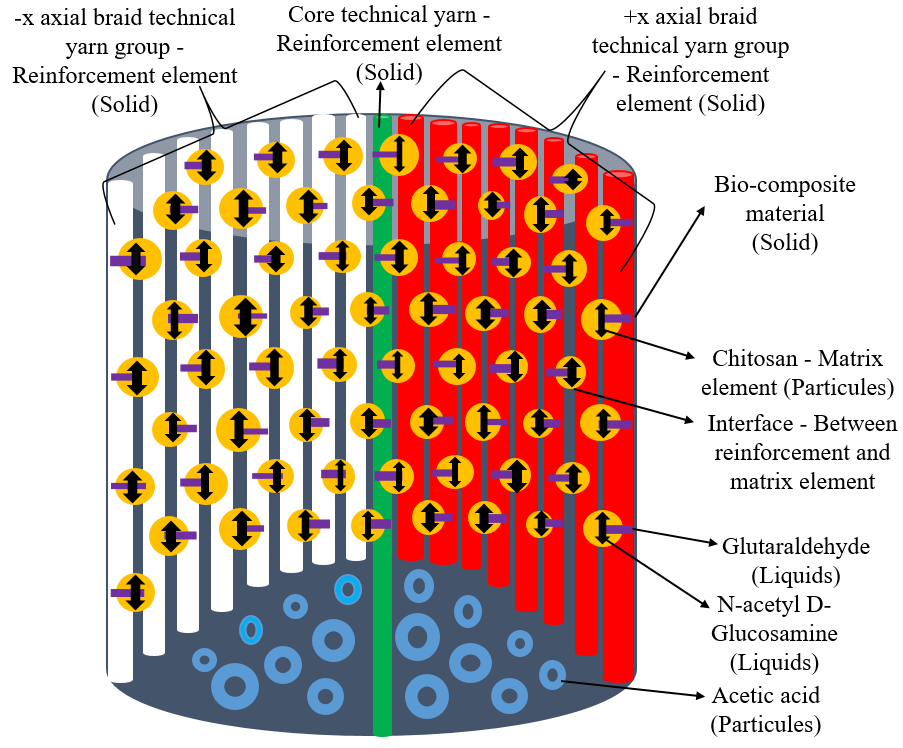
Figure 1. The Main Basic Structure of Bio-composite Materials.
The basic technical structure for the reinforcement elements and matrix elements in bio-composite material was shown in Figure 2.
|
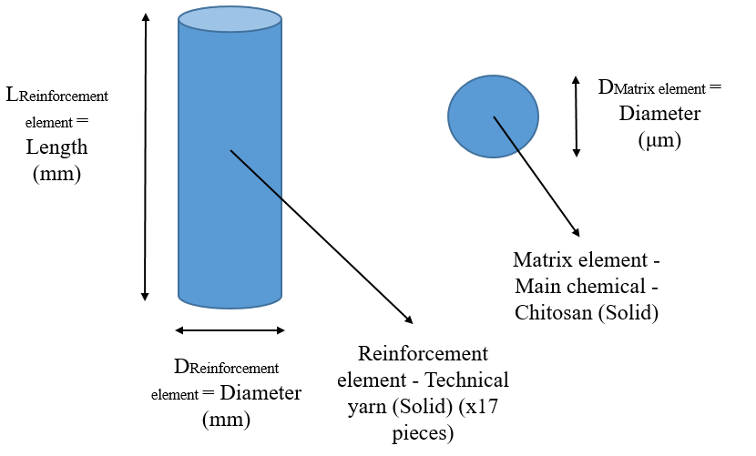
Figure 2. The basic technical structure for the reinforcement elements and matrix elements in bio-composite material.
The micro-mechanics of composite materials with braiding technologies have effected by production methods, and production process parameters such as temperature, time and pressure values, yarn types, yarn diameters, yarn numbers, yarn packing factors, number of filaments, filament orientation angles, yarn - yarn friction coefficients, mechanical properties of the yarns (density, elasticity modulus, shear modulus, tensile strength, shear strength, percentage elongation at break, poissonʼs ratio), number of braid yarns, braid angles, number of braid layers, and determined fiber - volume ratios. Moreover, the type of chemical, and mechanical properties of the chemical (density, modulus of elasticity, shear modulus, tensile strength, shear strength, percentage elongation at break, Poissonʼs ratio), are affect the micro-mechanics of composite materials with braiding technologies. The braid angle is generally the most effective factor[2-15]. The high - performance (Technical) yarns as reinforcement elements were used for artificial ACL grafts were shown in Table 4, respectively. The mechanical properties of technical yarns according to TS EN ISO 13934-1 were shown in Table 5, respectively. Each technical yarn was used for each sample code in its technical yarn type and the same yarn count for both center and braid yarns.
Table 4. The High - Performance (Technical) Yarns as Reinforcement Elements were Used for Artificial ACL Grafts
Sample code in braiding samples |
Type of technical yarn in braiding samples |
Total yarn number (core and braid) in braiding samples |
Core yarn count (dtex), and filament number in braiding samples |
Braid yarn count (dtex), and filament number in braiding samples |
Braid angle (°) in braiding samples |
Type of braiding construction in braiding samples |
T1 |
UHMWPE |
1+16=17 |
445/96 |
445/96 |
45° |
Diamond |
T2 |
UHMWPE |
1+16=17 |
445/96 |
445/96 |
45° |
Double braided |
T3 |
PPD-T |
1+16=17 |
1670/244 |
1670/244 |
45° |
Diamond |
T4 |
PPD-T |
1+16=17 |
1670/244 |
1670/244 |
45° |
Double braided |
T5 |
HT PET |
1+16=17 |
1670/244 |
1670/244 |
45° |
Diamond |
T6 |
HT PET |
1+16=17 |
1670/244 |
1670/244 |
45° |
Double braided |
Table 5. The Mechanical Properties of Technical Yarns According to TS EN ISO 13934-1
Type of technical yarns |
Maximum braking force (N) (Axial direction) |
Percent maximum breaking elongation (%) (Axial direction) |
Tensile strength (MPa) (Axial direction) |
UHMWPEF |
7,330 |
1,036 |
971.495,294 |
PPD-TF |
26,563 |
1,063 |
938.117,048 |
High tenacity polyethylene terephthalate fiber (HT PETF) |
8,250 |
1,866 |
291.362,634 |
The chemical recipe of bio - chemical finishing as matrix elements was liquid (Flotte) ratio: 1:10, chitosan (85% purity) with powder form 2%, N - Acetyl D - Glucosamine (2% purity) 7% with liquid form, glutaraldehyde (99% purity) with liquid form 25% and acetic acid (80% purity) with liquid form 1%.
2.2 Braiding Production Process
The bobbins in the creel were transferred to the braids bypassing the control of the yarn tension meter in the braiding production preparation and its process. UHMWPE, PPD-T, and HT PET were used as core and braid yarns with different yarn counts (dtex). The braiding yarn transfer process was carried out on a YHUT-6-1 (90) braiding transfer machine belonging to Arer Tres Braiding Machine Industry and Trade Limited Company. 3D braiding production was carried out on a YHUT-16-3 (90) braiding machine belonging to Arer Tres Braiding Machine Industry and Trade Limited Company. They were carried out in Bursa Bağcı Elyaf and Apparel Materials Construction Industry Trade Limited Company in Bursa. The braiding production process was shown in Figure 3, respectively.
|
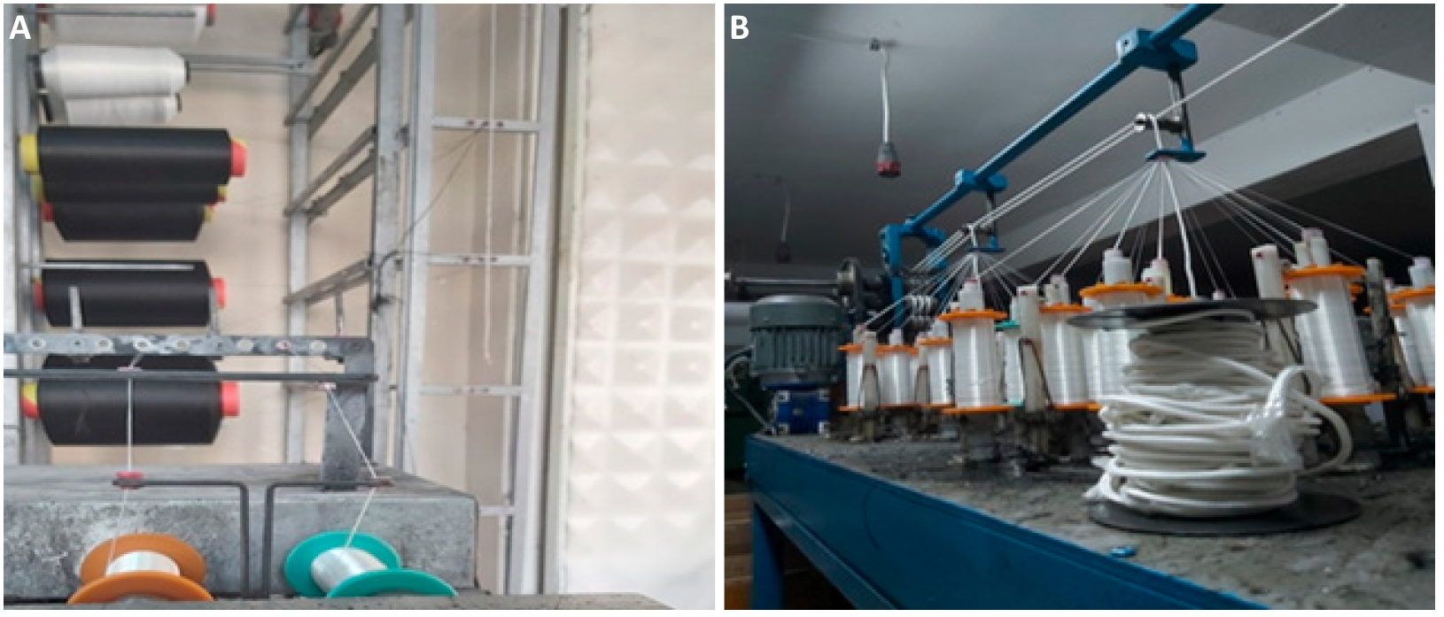
Figure 3. Braiding production process. (A) preparation process to 3D braiding process; (B) 3-D braiding production process.
2.3 Bio - chemical Finishing Process
pH values of the solution were measured by the P - 510 portable pH meter of Peak Instruments INC. Also, the solution ambient temperature was measured with the help of a mercury thermometer (Max operating temperature: 115℃). All samples were performed at the same time (All in one) method for preparation of the biochemical solution. All chemicals in liquid form were prepared by the bath (flotte) recipe with the help of beakers. Chemicals with powder form and weight measurements were taken with the help of a weight device and then added to the solution with the help of beakers. The volume of the solution was determined as 1L. All chemicals were prepared by the bio - chemical finishing process recipe. Then, the solution was prepared in a large 1L beaker. The bio - chemical finishing process was carried out at Bursa Uludağ University in Bursa. Process parameters of the bio - chemical finishing chemical recipe were like these temperature (Tort) of 70℃, time (t) for 3h at pH between 5 and 5.5. The bio - chemical finishing process was shown in Figure 4, respectively.
|
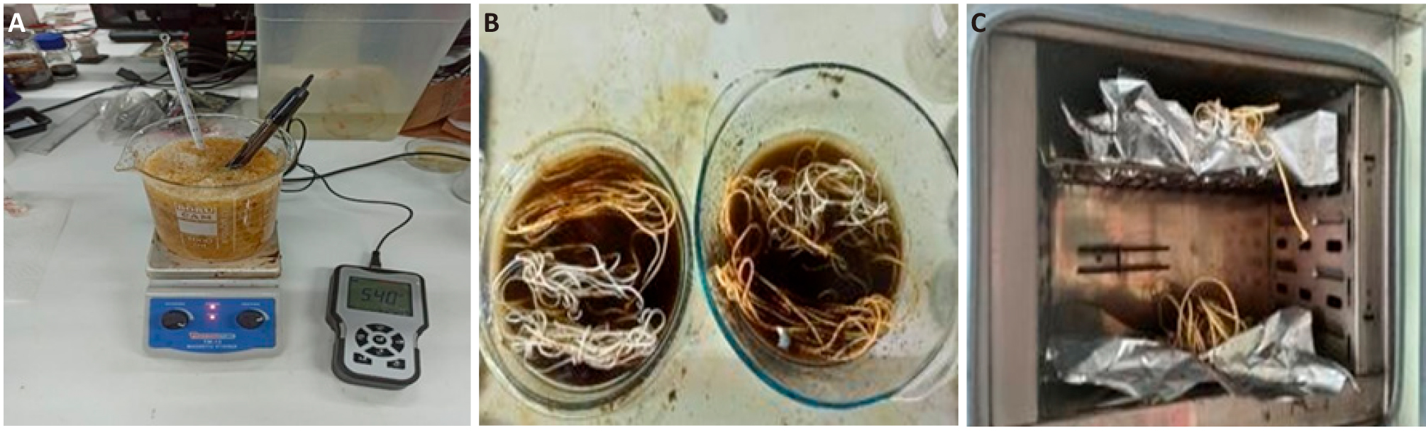
Figure 4. The bio - chemical finishing process. (A) bio - solution preparation process; (B) bio - padding process; (C) bio - thermosetting process.
2.4 Post Operations such as are PBS Bio - chemical (in - vitro condition) Process, Fixing, and Ethylene Oxide (EtO) Sterilization Processes
PBS was a bio - chemical and it was used to provide the in - vitro environment and a pH 7.2. 12 samples were used for a total of 2L water volume, 1 tablet being 100mL. In this process, 6 samples were used in each section so that they were applied to 2 times for all samples. Afterward, post - treatment was applied at 115℃ for 10min in an oven at Bursa Uludağ University. Ethylene oxide (ETO) sterilization was applied to all finished samples. (under 16h, 1atm pressure). EtO sterilization was carried out in Teknomar Companyʼs ETO C 1, 445 brand - type EtO sterilization device. It was carried out at Çekirge State Hospital in Bursa. Post operations were shown in Figure 5, respectively.
|
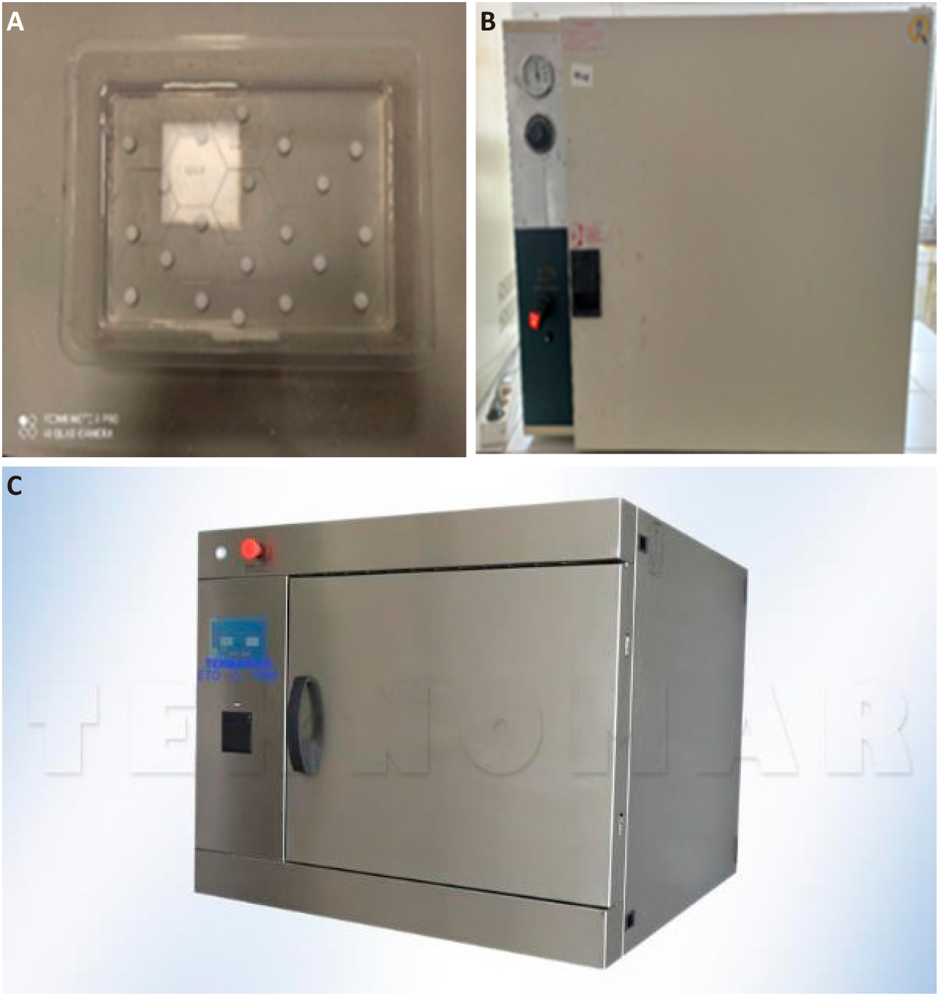
Figure 5. Post operations. (A) applied PBS chemical; (B) drying and fixing processes; (C) ethylene oxide sterilization process.
2.5 Optical Microscope Images
Optical microscope images, which had 30 times as magnification ratio, were taken with an Olympos brand instrument. It was shown in Figure 6. Optical microscope images of raw and bio - finished with EtO sterilization for all samples were shown in Figure 7 and Figure 8, respectively.
|
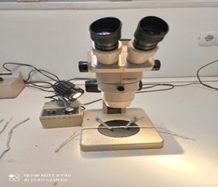
Figure 6. Olympos brand optical microscope instrument (30 times as magnification ratio).
|
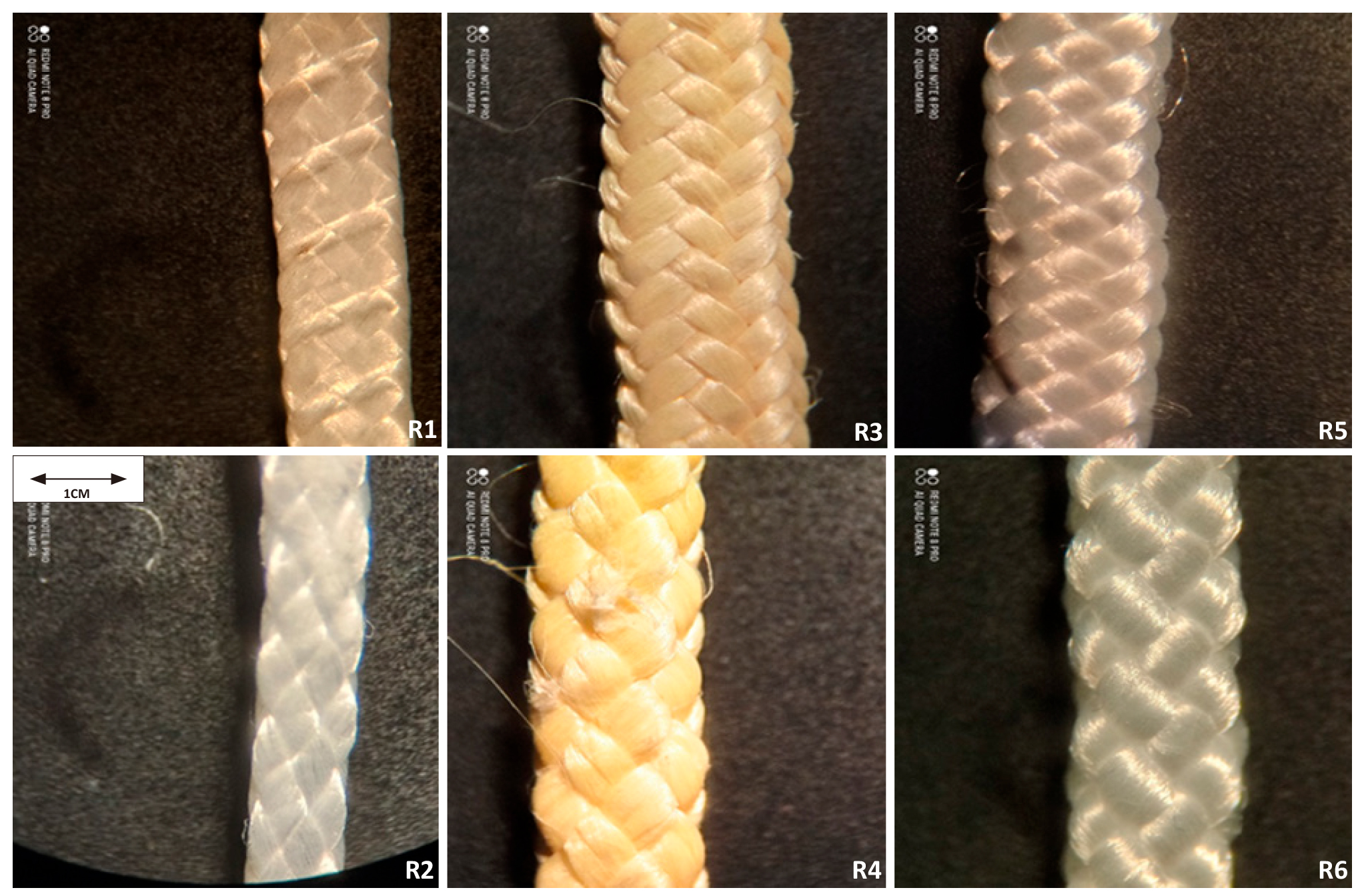
Figure 7. All raw samples (30 times as magnification ratio).
|
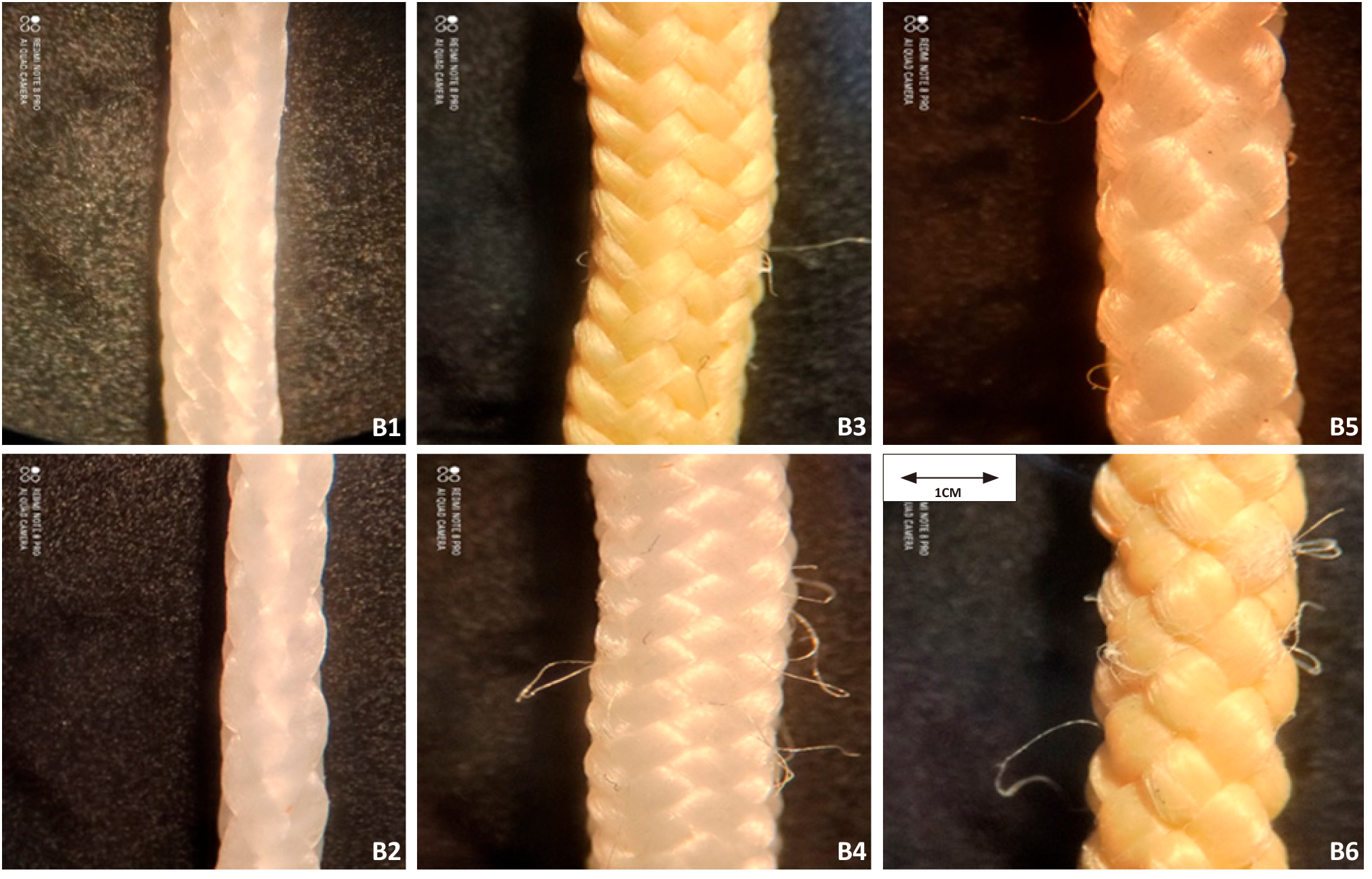
Figure 8. All bio - finished samples (30 times as magnification ratio).
2.6 Weight (g/m) and Diameter (mm) Measurements
Weight (g/m) measurements were taken using a Mettler PJ 300 instrument. Diameter (mm) measurements were taken using an R&B Cloth Thickness Tester instrument. Braiding thickness was determined by measuring the distance between the top and bottom faces of the braiding structures under 1±0.01kPa pressure in end of during 30s. Weight (g/m) and Diameter (mm) Measurements were shown in Figure 9, respectively.
|
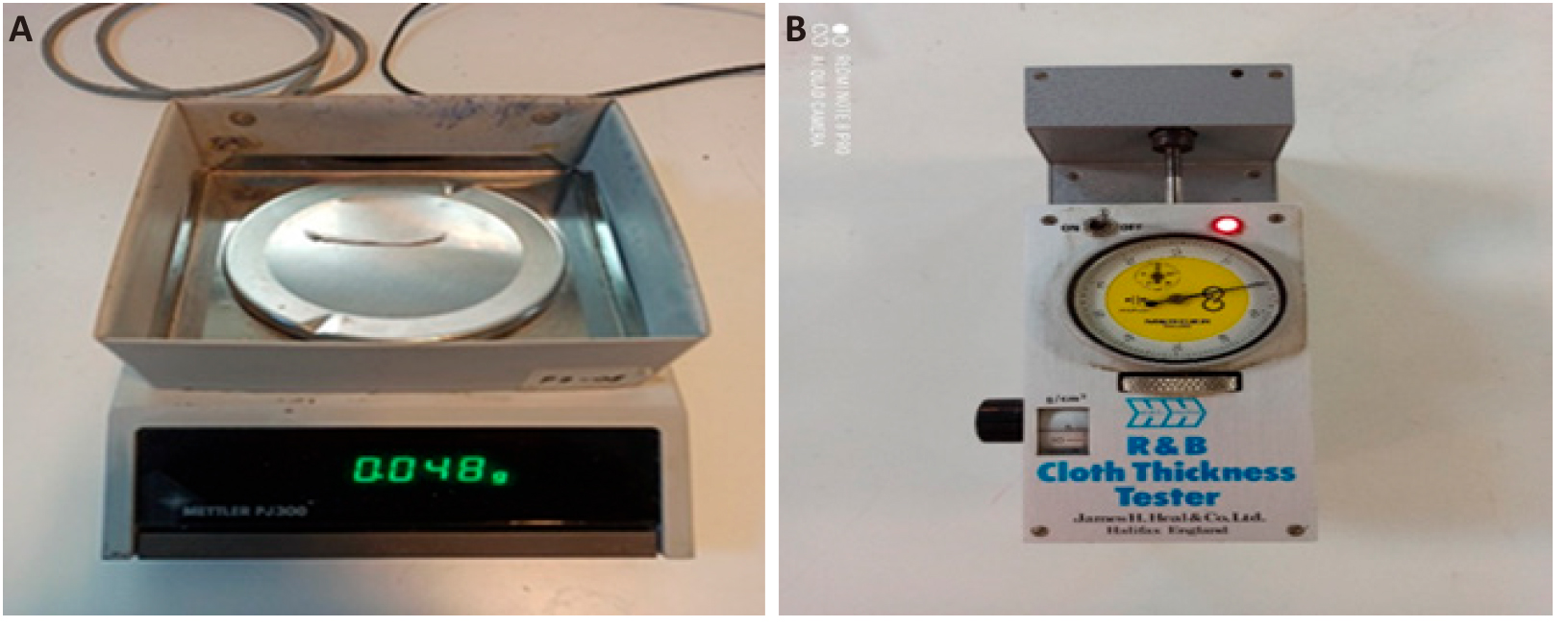
Figure 9. Weight (g/m) and Diameter (mm) Measurements. (A) Mettler PJ 300 instrument; (B) R&B Cloth Thickness Tester.
Table 6. The Weight (g/m) and Diameter (mm) Values of Raw Materials and Bio - Chemical Finished Bio - Materials in Braiding Samples
Sample code in braiding samples |
Weight (g/m) values of raw materials (R) in braiding samples |
Weight (g/m) values of bio - chemical finished bio - materials (B) in braiding samples |
Diameter (mm) values of raw materials (R) in braiding samples |
Diameter (mm) values of bio - chemical finished bio - materials (B) in braiding samples |
T1 |
0.928 |
1.380 |
0.530 |
0.974 |
T2 |
0.896 |
1.233 |
0.610 |
0.936 |
T3 |
3.788 |
5.720 |
2.128 |
2.586 |
T4 |
4.336 |
5.560 |
1.888 |
2.652 |
T5 |
3.984 |
5.773 |
2.072 |
2.294 |
T6 |
3.968 |
5.120 |
2.100 |
2.316 |
In line with the experimental results, the diameter (mm) values of all samples produced were found to be lower than the diameter (mm) values of the natural ACL graft, which is between 4 and 10mm (8) for both raw and bio - finished samples with applied EtO sterilization. Some assumptions were accepted in the application of Equation (1) and were as follows these reinforcement elements in bio-composite materials were assumed that all the fibers and yarns that make up the 3-D braiding structure were parallel to each other, continuous, linear, and of equal length for the reinforcement elements. Their cross - sections had smooth cylindrical geometry. They were accepted as anisotropic material. Modulus of elasticity, shear modulus, thermal expansion coefficients, and Poissonʼs ratios were neglected. The effects of air gap and EtO sterilization on the surface morphology of fibers, yarns, and 3-D braiding structures were neglected. About matrix elements in bio-composite materials were assumed matrix elements (total) were thought of as a single matrix element. It was assumed that acetic acid (80%) had completely evaporated. It was assumed that the chemicals (in powder form) had a constant particle size and were dispersed homogeneously. Interfacial bond=1 (perfect) was assumed. That was, it stayed that way during deformation. Thus, fiber - interphase - matrix debonding or matrix microcracking was not taken into account and the resulting composite was void - free. A uniaxial analysis was performed perpendicular to the fiber axis. The effects of all bio - chemical process parameters such as temperature, time, pressure, and pH were assumed constant.
2.7 Calculation of Fiber - to - Volume Ratio for bio-composite Material Samples
|
0.928g weight was for 1m. Since it had 1m=100cm. It must be divided by the coefficient 100/5=20 for 50mm=5cm so that 0.928g/20=0.0464g. (Applied to T1H samples due to its length being 50mm=5cm). Since 17 technical yarns were used in the 3-D braiding structure, the density value of 0.97g/cm3 was multiplied by the coefficient of 17. It was calculated as like Vf1=0.0464/17. 0.97=0.0464/16.49=2.81x10-3cm3. (Applied to T1H samples due to its length being 50mm=5cm long).
Before the matrix element (Total) can be calculated, the volume of the bio-composite material must be calculated like these that it was Vm1=Vc1-Vf1 so that Vc1=Vf1+Vm1=mf1×ρf1+mm1×ρm1 (1) 1.380g weight was for 1m. Since it had 1m=100cm. It must be divided by the coefficient 100/5=20 for 50mm=5cm. 1.380g/20=0.069g. (Applied to T1H samples due to its length being 50mm=5cm long). According to Vc1=mc1/ρc1, Since 17 technical yarns were used in the 3-D braiding structure, the density value of 0.97g/cm3 was multiplied by the coefficient of 17. It was Vc1=0.069/(17. 0.97)=0.069/16.4 =4.18×10⁻³cm3. (Applied to T1H samples due to its length being 50mm=5cm long). It was Vm1=Vc1–Vf1 so that Vm1=4.18×10⁻³-2.81×10-3=1.37×10⁻³ calculated as the fiber-volume ratio was Vc1 = Vf1 + Vm1 = 2.81×10⁻³ + 1.37×10-3=4.18×10⁻³ so that it was calculated % in that Vf1=Vf1/Vc1×100=2.81x10-3/4.18×10-3×100=67.225%. It was calculated 67.225% for reinforcement elements. Also, % in Vm1=Vm1/Vc1×100=1.37×10-3/4.18×10-3×100=32.775%. It was calculated 32.775% for the matrix element.
Equation (1) was applied to all samples. According to the Equation (1), the experimental technical results of bio-composite materials in all 3-D braiding samples were shown in Table 7 in the results and discussion. Technical information explanations as graphs were shown according to their experimental results in Figures 10, 11, and 12 in the results and discussion, respectively.
Table 7. The Experimental Technical Results of bio-composite Materials in all 3-D Braiding Samples
Sample code in braiding samples |
Total volume of composite material (cm3) and fiber - volume percent (%) |
Total volume of reinforcement element (Technical yarns) (cm3) and fiber - percentage by volume (%) |
Total volume of matrix elements (all chemicals used) (10-3cm3) and matrix - percentage by volume (%) |
T1 |
4.18×10⁻³/100 |
2.81×10⁻³/67.225 |
1.37×10⁻³/32.775 |
T2 |
3.76×10⁻³/100 |
2.72×10⁻³/72.340 |
1.04×10⁻³/27.660 |
T3 |
11.68×10⁻³/100 |
7.72×10⁻³/66.096 |
3.96×10⁻³/33.904 |
T4 |
11.35×10⁻³/100 |
8.86×10⁻³/78.061 |
2.49×10⁻³/21.939 |
T5 |
12.27×10⁻³/100 |
8.48×10⁻³/69.112 |
3.79×10⁻³/30.888 |
T6 |
10.91×10⁻³/100 |
8.44×10⁻³/77.360 |
2.47×10⁻³/22.640 |
|
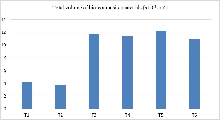
Figure 10. The total volume of bio-composite materials (×10-3cm3).
|
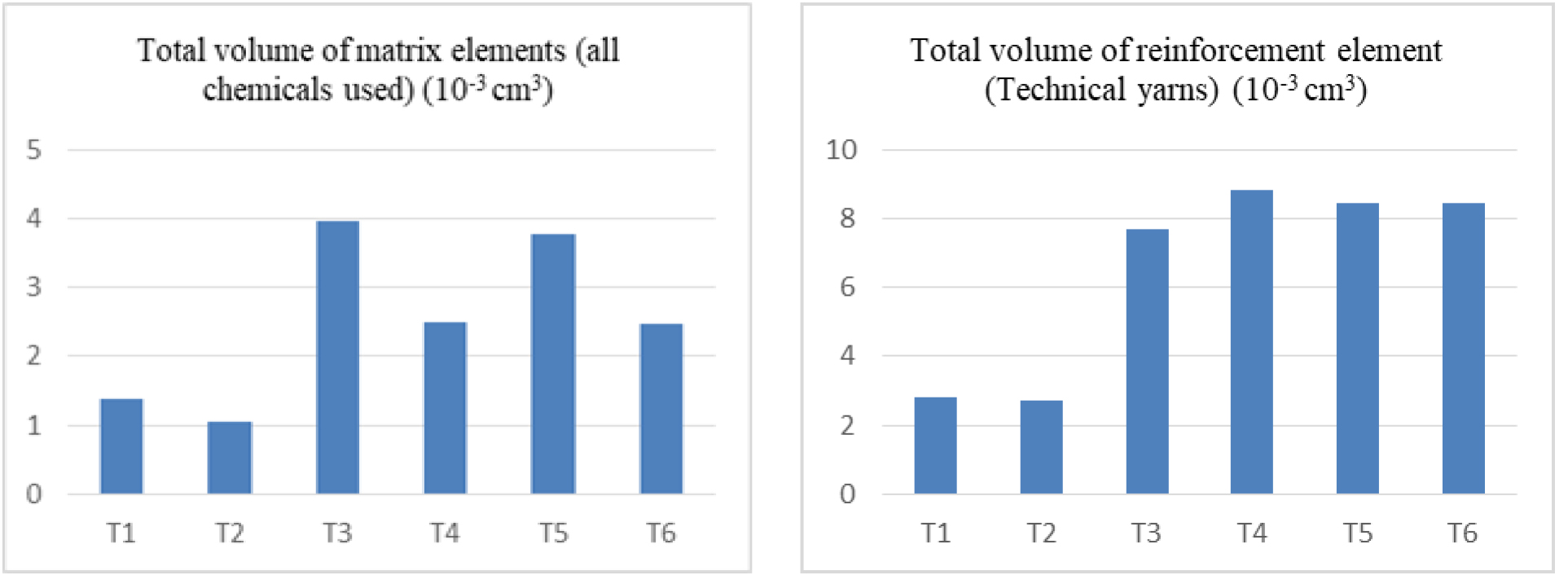
Figure 11. The total volume of reinforcement elements (Technical yarns), and matrix elements (all chemicals used) (x10-3cm3).
|
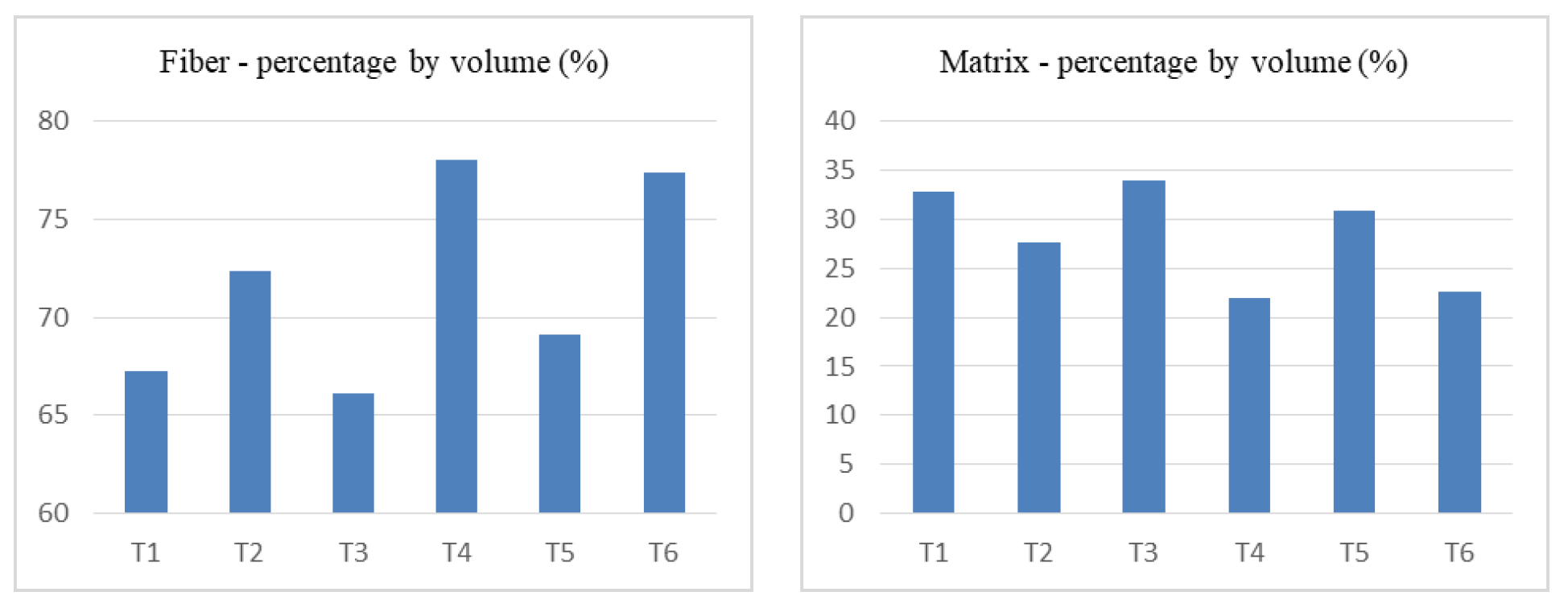
Figure 12. The fiber - percentage, and matrix - percentage by volume (%).
3 RESULTS AND DISCUSSION
3.1 Weight (g/m) and Diameter (mm) Measurements
The type of yarn, the mechanical properties of the yarn, the number of yarns used, the pitch length, the pitch number, the braiding construction, the braid angle, and the fiber - to - volume ratio were extremely effective factors in the micro-mechanics of composite materials with braiding structured. There were various composite material applications, generally based on CF fiber with a high modulus of elasticity and thermosetting epoxy resin, with a 30° braid angle. The fiber - to - volume ratio was between 39 and 58 in composite materials with braiding structures[2-15].
Moreover, it was observed that as the 30° braid angle increased, the elasticity modulus and tensile strength increased in the axial direction, but the maximum elongation at break decreased[10,14]. Thus; UHMWPEF, PPD-TF, and HT PETF with high elasticity modulus and tensile strength values in the axial direction, such as 45°braid angle with CF, and GF, and which can be used in bio-composite structures, were used as reinforcement elements in this experimental study. Moreover, CHI was used as the main matrix element and GA was used as a biological cross - linker to provide a biological advantage in this experimental study. The fiber - to - volume ratios of bio-composite materials with braiding structure were observed between 67 and 78 in this experimental study. The matrix - to - volume ratios of bio-composite materials with braiding structure were observed between 22 and 34 in this experimental study. The total volumes of bio-composite materials with braiding structure were observed between 3.76 and 12.27 in this experimental study. The total volume of bio-composite materials of all samples was T5>T3>T4>T6>T1>T2, respectively.
The highest fiber - volume ratio of all samples was T4>T6>T2>T5>T1>T3, respectively. The highest matrix - volume ratio of all samples was T3>T1>T5>T2>T6>T4, respectively.
3.2 Statistical Analysis Results of Calculations of micro-mechanics for Artificial ACL Grafts
The analyses of variance were executed to predict the significance of the process variables (x2). Their interaction form was presented on calculations of micro-mechanics for artificial ACL grafts with a 99% confidence level. Process variables were yarn type, yarn count, or braiding construction. Non - repetitive two - factor ANOVA analysis was calculated in the Excel 2013 program. The statistical results for non - repetitive two - factor ANOVA analysis for calculations of micro-mechanics for artificial ACL grafts were calculated in Table 8.
Table 8. The Statistical Results for Non - Repetitive Two - Factor ANOVA Analysis for Calculations of micro-mechanics for Artificial ACL Grafts
Anova: Two Factors Without Replication |
||||||
Conclusion |
Say |
Total |
Average |
Variance |
|
|
Line 1 |
3 |
8,36 |
2,786,667 |
1,974,433 |
|
|
Line 2 |
3 |
7,52 |
2,506,667 |
1,883,733 |
|
|
Line 3 |
3 |
23,36 |
7,786,667 |
1,490,293 |
|
|
Line 4 |
3 |
22,7 |
7,566,667 |
2,087,943 |
|
|
Line 5 |
3 |
2,454 |
818 |
180,451 |
|
|
Line 6 |
3 |
2,182 |
7,273,333 |
1,882,923 |
|
|
Column 1 |
6 |
5,415 |
9,025 |
1,554,643 |
|
|
Column 2 |
6 |
3,903 |
6,505 |
852,927 |
|
|
Column 3 |
6 |
1,512 |
252 |
144,056 |
|
|
ANOVA |
||||||
Variance Source |
SS |
df |
MS |
F |
P - value |
F criterion |
Lines |
1,036,429 |
5 |
2,072,857 |
8,659,119 |
0,002,115 |
5,636,326 |
Columns |
1,290,913 |
2 |
6,454,565 |
2,696,319 |
9,37E - 05 |
7,559,432 |
Error |
2,393,843 |
10 |
2,393,843 |
|
|
|
Total |
256,726 |
17 |
|
|
|
|
The process parameters of yarn type, yarn count, or braiding construction (x2 factors) were significant, and effective on the total volume, the highest fiber - volume ratio, and the highest matrix - volume ratio of bio-composite materials of artificial ACL grafts groups. Because the P - value was <0.01.
Technical comments for the total volume of bio-composite materials of all samples. It was observed to have the highest bio-composite volume ratio in HT PET structures with diamond construction. It was thought for reason that the diamond 3-D braiding construction had a shorter pitch length and more pitch number than the double - layered 3-D braiding construction. It was observed that UHMWPE technical yarns were very low compared to all other technical yarn samples for bio-composite volume ratios because it had the lowest density and thinner yarn number. Its double - layered construction had also the lowest total volume of bio-composite materials, too. Its unit volume model was also so small, too. Moreover, double - layered 3-D braiding construction had a longer pitch length and less pitch number than the diamond 3-D braiding construction.
It was observed that the diamond braiding construction had a higher total volume of bio-composite materials compared to the double - layer braiding construction. Moreover, the thicker yarn count had also a higher total volume of bio-composite materials compared to the thinner yarn count, too.
Technical comments for the highest fiber - volume ratio and the highest matrix - volume ratio of all samples. It was observed that PPD-T and HT PET technical yarns had a higher percentage of reinforcement elements than UHMWPE technical yarns in double - layered 3-D braiding construction. It was observed that UHMWPE technical yarns had a higher percentage of matrix elements than PPD-T and HT PET technical yarns in double - layered 3-D braiding construction. Moreover, their yarn counts were also higher than UHMWPE technical yarns, too. It was observed that the highest reinforcement element ratio and the lowest matrix element ratio was the PPD-T in the double - layered 3-D braiding construction for thick yarn counts. It was also observed that the lowest reinforcement element ratio and the highest matrix element ratio was the PPD-T in the diamond 3-D braiding construction for thick yarn counts, too. Diamond 3-D braiding construction had a shorter pitch length and more pitch number compared to the double - layered 3-D braiding construction.
4 CONCLUSIONS
The fiber - to - volume ratios of bio-composite materials with braiding structure were observed between 67 and 78 in this experimental study. The matrix - to - volume ratios of bio-composite materials with braiding structure were observed between 22 and 34 in this experimental study. The total volumes of bio-composite materials with braiding structure were observed between 3.76 and 12.27 in this experimental study. The process parameters of yarn type, yarn count, or braiding construction (x2 factors) were significant, and effective on the total volume, the highest fiber - volume ratio, and the highest matrix - volume ratio of bio-composite materials of artificial ACL grafts groups. Because the P - value was < 0.01. Thick yarn count, and PPD-T or HT PET type yarns or double - layer braiding construction had a higher effect on the total volume, fiber - volume ratio, and matrix - volume ratio of braiding structured bio-composite materials. The number of center and braid yarns, yarn count and braid angle should be increased to increase the fiber - to - volume ratios, and the total volumes of bio-composite materials with braiding structure.
Acknowledgements
This work was supported by the Bursa Uludağ University registered under the number No: T.C B.U.Ü BAP OUAP (MH) 2020/9. All raw samples were collected in Bursa Bağcı Elyaf and Apparel Materials Construction Industry Trade Limited Company in Bursa with the help of Mr. Fedahi KILIÇAY who is head of the manufacturing department.
Conflicts of Interest
The author declared that he has no known competing financial interests or personal relationships that could have appeared to influence the work reported in this paper.
Author Contribution
Turşucular ÖF was responsible for all the work on this article.
Abbreviation List
C, Carbon
CF, Carbon fiber
GF, Glass fiber
HDPP, Heavyweight polypropylene
HT PET, High tenacity polyethylene terephthalate
HT PETF, High tenacity polyethylene terephthalate fiber.
LDPP, Lightweight polypropylene
PE, Polyethylene
PET, Polyethylene terephthalate
PP, Polypropylene
PPD-T, Polyparaphenylene terephthalamide
PPD-TF, Polyparaphenylene terephthalamide fiber
PTFE, Polytetrafluoroethylene
UHMWPE, Ultra high molecular weight polyethylene
UHMWPEF, Ultra high molecular weight polyethylene fiber
References
[1] Rajak DK, Pagar DD, Kumar R et al. Recent progress of reinforcement materials: a comprehensive overview of composite materials. J Mater Res Technol, 2019; 8: 6354-6374.[DOI]
[2] Ahn H, Kim KJ, Park SY et al. 3D braid scaffolds for regeneration of articular cartilage. J Mech Behav Biomed, 2014; 34: 37-46.[DOI]
[3] Ahn H, Yu WR. Mechanical analysis of 3D braided and woven composites using fiber-based continuum analysis. Compos Struct, 2017; 160: 1105-1118.[DOI]
[4] Qiwei G, Zhang G, Li J. Process parameters design of a three-dimensional and five-directional braided composite joint based on finite element analysis. Mater Design, 2013; 46: 291-300.[DOI]
[5] Hao W, Yuan Y, Yao X et al. Computational analysis of fatigue behavior of 3D 4-directional braided composites based on unit cell approach. Adv Eng Softw, 2015; 82: 38-52.[DOI]
[6] Li DS, Lu ZX, Chen L et al. Microstructure and mechanical properties of three-dimensional five-directional braided composites. Int J Solids Struct, 2009; 46: 3422-3432.[DOI]
[7] Littell JD, Binienda WK, Roberts GD et al. Characterization of damage in triaxial braided composites under tensile loading. J Aerospace Eng, 2009; 22: 270-279.[DOI]
[8] Wang X, Cai D, Li C et al. Failure analysis of three-dimensional braided composite tubes under torsional load: Experimental study. J Reinf Plast Comp, 2017; 36: 878-888.[DOI]
[9] Wang X, Cai D, Silberschmidt V et al. Tensile properties of 3D multi-layer wrapping braided composite: Progressive damage analysis. Compos Part B-Eng, 2019; 176: 107334.[DOI]
[10] Wu L, Zhang F, Sun B et al. Finite element analyses on three-point low-cyclic bending fatigue of 3-D braided composite materials at the microstructure level. Int J Mech Sci, 2014; 84: 41-53.[DOI]
[11] Xu K, Xu XW. Finite element analysis of mechanical properties of 3D five-directional braided composites. Mat Sci Eng A, 2008; 487: 499-509.[DOI]
[12] Zhai J, Zeng T, Xu GD et al. A multi-scale finite element method for failure analysis of three-dimensional braided composite structures. Compos Part B-Eng, 2017; 110: 476-486.[DOI]
[13] Zhang C, Binienda WK, Goldberg RK et al. Meso-scale failure modeling of single layer triaxial braided composite using finite element method. Compos Part A-Appl S, 2014; 58: 36-46.[DOI]
[14] Zhang C, Li N, Wang W et al. Progressive damage simulation of triaxially braided composite using a 3D mesoscale finite element model. Compos Struct, 2015; 125: 104-116.[DOI]
[15] Dang H, Zhao Z, Liu P et al. A new analytical method for progressive failure analysis of two-dimensional triaxially braided composites. Compos Sci Technol, 2020; 186: 107936.[DOI]
[16] Kundalwal SI. Review on Micromechanics of Nano-and Micro-Fiber Reinforced Composites. Polym Composite, 2018; 39: 4243-474.[DOI]
[17] Amiri A, Ulven CA. Advanced method for void fraction evaluation of natural composites using micro-ct technology: Proceedings of Sampe Conference and Exhibition. California, USA, 23-26 May 2016.[DOI]
[18] Silva M, Ferreira FN, Alves NM et al. Biodegradable polymer nanocomposites for ligament/tendon tissue engineering. J Nanobiotechnol, 2020; 18: 1-33.[DOI]
[19] Barnett S, Murray MM. Updates on Anterior Cruciate Ligament Repair Techniques. Oper Techn Sport Med, 2020; 28: 1-6.[DOI]
[20] Meister M, Koch J, Amsler F et al. ACL suturingusing dynamic intraligamentary stabilisation showing good clinical outcome but a high reoperation rate: a retrospective independent study. Knee Surg Sport Tr A, 2018; 26: 655-659.[DOI]
[21] May C, Gueorguiev B, Heuberger R et al. Low metallic wear of dynamic intraligamentary stabilization. Tribol Int, 2017; 109: 217-221.[DOI]
[22] Henle P, Röder C, Perler G et al. Dynamic Intraligamentary Stabilization (DIS) for treatment of acute anterior cruciate ligament ruptures: case series experience of the first three years. Bmc Musculoskel Dis, 2015; 16: 1-9.[DOI]
[23] Legnani C, Ventura A, Terzaghi C et al. Anterior cruciate ligament reconstruction with synthetic grafts A review of the literature. Int Orthop, 2010;34: 465-471.[DOI]
[24] Marieswaran M, Jain I, Garg B et al. A Review on Biomechanics of Anterior Cruciate Ligament and Materials for Reconstruction. Appl Bionics Biomech, 2018; 4657824: 1-14.[DOI]
[25] Shirazi AN, Chrzanowski W, Khademhosseini A et al. Anterior cruciate ligament: structure, injuries and regenerative treatments. Eng Mineralized Load Bear Tissues, 2015; 881: 161-186.[DOI]
[26] Hoogeslag RAG, Brouwer RW, Boer BC et al. Acute anterior cruciate ligament rupture: repair or reconstruction? Two-year results of a randomized-controlled clinical trial. Am J Sport Med, 2019; 47: 567-577.[DOI]
[27] Markatos K, Kaseta MK, Lallos SN et al. The anatomy of the ACL and its importance in ACL reconstruction. Eur J Orthop Surg Tr, 2013; 23: 747-752.[DOI]
[28] Häberli J, Jaberg L, Bieri K et al. Reinterventions after dynamicintraligamentary stabilization in primary anterior cruciate ligament repair. Knee, 2018; 25: 271-278.[DOI]
[29] Gloy YS, Loehrer M, Lang B et al. Tubular Woven Narrow Fabrics for Replacement of Cruciate Ligaments. Ann Biomed Eng, 2013; 41: 1950-1956.[DOI]
[30] Li H, Chen S. Biomedical coatings on polyethylene terephthalate artificial ligaments. J Biomed Mater Res A, 2015; 103: 839-845.[DOI]
[31] Legnani C, Ventura A, Terzaghi C et al. Anterior cruciate ligament reconstruction with synthetic grafts. A review of the literature. Int Orthop, 2010; 34: 465-471.[DOI]
[32] Bach JS, Cherkaoui M, Corté L et al. Design considerations for a prosthetic anterior cruciate ligament. J Med Devices, 2012; 6: 1-9.[DOI]
[33] Li S, Wang S, Liu W et al. Current strategies for enhancement of the bioactivity of artificial ligaments: A mini-review. J Orthop Transl, 2022; 36: 205-215.[DOI]
[34] Laurencin CT, Freeman JW. Ligament tissue engineering: an evolutionary materials science approach. Biomaterials, 2005; 26: 7530-7536.[DOI]
[35] Sun L, Huang L, Wang X et al. Synthesis and Structural Characterization of Sequential Structure and Crystallization Properties for Hydrophilic Modified Polyester. Polymers, 2020; 12: 1-18.[DOI]
[36] Zhang P, Han F, Li Y et al. Local delivery of controlled-release simvastatin to improve the biocompatibility of polyethylene terephthalate artificial ligaments for reconstruction of the anterior cruciate ligament. Int J Nanomed, 2016; 11: 465-478.[DOI]
[37] Wang CH, Guo ZS, Pang F et al. Effects of graphene modification on the bioactivation of polyethylene-terephthalate-based artificial ligaments. Acs Appl Mater Inter, 2015; 7: 15263-15276.[DOI]
[38] Rodrigues MT, Reis RL, Gomes ME. Engineering tendon and ligament tissues: present developments towards successful clinical products. J Tissue Eng Regen M, 2013; 7: 673-686.[DOI]
[39] Iliadis D, Bourlos DN, Mastrokalos DS et al. LARS artificial ligament versus ABC purely polyester ligament for anterior cruciate ligament reconstruction. Orthop J Sports Med, 2016; 4: 1-10.[DOI]
[40] Parchi PD, Gianluca C, Dolfi L et al. Anterior cruciate ligament reconstruction with LARS™ artificial ligament results at a mean follow-up of eight years. Int Orthop, 2013; 37: 1567-1574.[DOI]
[41] Jia Z, Xue C, Wang W et al. Clinical outcomes of anterior cruciate ligament reconstruction using LARS artificial graft with an at least 7-year follow-up. Medicine, 2017; 96: 1-6.[DOI]
[42] Batty LM, Norsworthy CJ, Lash NJ et al. Synthetic devices for reconstructive surgery of the cruciate ligaments: a systematic review. Arthroscopy, 2015; 31: 957-968.[DOI]
[43] Kohl S, Evangelopoulos DS, Schär MO et al. Dynamic intraligamentary stabilization: initial experience with treatment of acute ACL ruptures. Bone Joint J B, 2016; 98: 793-798.[DOI]
[44] Osti M, Attal RE, Doskar W et al. The high complication rate following dynamic intraligamentary stabilization for primary repair of the anterior cruciate ligament. Knee Surg Sport Tr A, 2019; 27: 29-36.[DOI]
[45] Evangelopoulos DS, Kohl S, Schwienbacher S et al. Collagen application reduces complication rates of mid-substance ACL tears treated with dynamic intraligamentary stabilization. Knee Surg Sport Tr A, 2017; 25: 2414-2419.[DOI]
[46] Kawakami Y, Nonaka K, Fukase ND et al. A cell-free biodegradable synthetic artificial ligament for the reconstruction of anterior cruciate ligament in a rat model. Acta Biomater, 2021; 121: 275-287.[DOI]
[47] Guo D, Wang S, Yin Y et al. Preparation of three-dimensional multilayer ECM-simulated woven/knitted fabric composite scaffolds for potential tissue engineering applications. Text Res J, 2020;90: 925-936.[DOI]
[48] Shankaran V, Weber DJ, Reed RL et al. Review of available prosthetics for ventral hernia repair. Ann Surg, 2011; 253: 16-26.[DOI]
[49] Ahrend MD, Ahmad S, Schröter S et al. Die Kreuzbandnahtmit[1TD$DIF] Stabilisierung (Ligamys):Eine Therapiem€oglichkeit beiakuten Kreuzbandrupturen. Sports Orthop Traumatol, 2018; 34: 108-114.[DOI]
[50] Herbort M, Domnick C. Remnant-Augmentation. Arthroskopie, 2018; 31: 201-206.[DOI]
[51] Erişen DE, Guisong G, Mingming L et al. A novel chitosan and polydopamine interlinked bioactive coating for metallic biomaterials. J Mater Sci-Mater M, 2022; 33: 1-12.[DOI]
[52] Lie GC, Mao Z, Shen J et al. Thermal dehydration treatment and glutaraldehyde cross-linking to increase the biostability of collagen-chitosan porous scaffolds used as dermal equivalent. J Biomat Sci-Polym E, 2003; 14: 861-874.[DOI]
[53] Pinto RV, Gomes PS, Fernandes MH et al. Glutaraldehyde-crosslinking chitosan scaffolds reinforced with calcium phosphate spray-dried granules for bone tissue applications. Mat Sci Eng C, 2020; 109: 1-13.[DOI]
[54] Liu Y, Ma L, Gao C. Facile fabrication of the glutaraldehyde cross-linked collagen/chitosan porous scaffold for skin tissue engineering. Mat Sci Eng C, 2012; 32: 2361-2366.[DOI]
[55] Puyana VP, Rosado MJ, Romero A et al. Crosslinking of hybrid scaffolds produced from collagen and chitosan. International Journal of Biological Macromolecules. Int J Biol Macromol, 2019; 139: 262-269.[DOI]
[56] Oryana A, Kamali A, Moshiri A et al. Chemical crosslinking of biopolymeric scaffolds: Current knowledge and future directions of crosslinked engineered bone scaffolds. Int J Biol Macromol, 2018; 107: 678-688.[DOI]
[57] Mendes GCC, Brandão TRS, Silva CLM. Ethylene oxide sterilization of medical devices: A review. Am J Infect Control, 2007; 35: 574-581.[DOI]
[58] Patil NA, Njuguna J, Kandasubramanian B. UHMWPE for biomedical applications: Performance and functionalization. Eur Polym J, 2020; 125: 1-22.[DOI]
[59] Baena JC, Wu J, Peng Z. Wear Performance of UHMWPE and Reinforced UHMWPE Composites in Arthroplasty Applications: A Review. Lubricants, 2015; 3: 413-436.[DOI]
[60] Chen X, Wang W, Li S et al. Fire safety improvement of para-aramid fiber in thermoplastic polyurethane elastomer. J Hazard Mater, 2017; 324: 789-796.[DOI]
[61] Prasad VV, Talupula SA. Review on Reinforcement of Basalt and Aramid (Kevlar 129) fibers. Mater Today: P, 2018; 5: 5993-5998.[DOI]
[62] Nisticò, R. Polyethylene terephthalate (PET) in the packaging industry. Polymer Test, 2020; 90: 106707.[DOI]
[63] Grishanov S. Chapter 2: Structure and properties of textile materials. In: Handbook of Textile and Industrial Dyeing. Woodhead Publishing: Southon, UK, 2011; 115-128.
[64] Kou SG, Peters LM, Mucalo MR. Chitosan: A review of sources and preparation methods. Int J Biol Macromol, 2021; 169: 85-94.[DOI]
[65] Jeon JG, Kim HC, Palem RR et al. Cross-linking of cellulose nanofiber films with glutaraldehyde for improved mechanical properties. Mater Lett, 2019; 250: 99-102.[DOI]
Copyright © 2024 The Author(s). This open - access article is licensed under a Creative Commons Attribution 4.0 International License (https://creativecommons.org/licenses/by/4.0), which permits unrestricted use, sharing, adaptation, distribution, and reproduction in any medium, provided the original work is properly cited.


