Transmission of Polarized Electrons through Multilayered Spintronics
Herbert P. Simanjuntak1*
1Department of Physics, University of Indonesia, Depok City, West Java, Indonesia
*Correspondence to: Herbert P. Simanjuntak, PhD, Department of Physics, University of Indonesia, JI. Lingkar, Pondok Cina, Beji District, Depok City, West Java, 16424, Indonesia; Email: herbert@ui.ac.id
DOI: 10.53964/jmn.2024001
Abstract
Objectives: We study transmission of polarized electrons through multilayered spintronics of the form of n-cell periodic (L/R)n and symmetric (L/R)nL multilayers. L and R are layers of ferromagnetic semiconductors or insulators. The multilayers are of arbitrary sizes with layer L of width a and layer R of width b. The number of cells n is arbitrary positive integer. For specific examples, we use ferromagnetic semiconductors Ga0.73Mn0.27N, In0.92Fe0.08As and Ga0.8Fe0.2N which have different sd-exchange energies. For the insulators, we use non-ferromagnetic insulator Al0.3Ga0.7As, and ferromagnetic insulator Al0.9Fe0.1Sb.
Methods: For the purpose of the study, we will calculate transmission coefficients of polarized electrons through each multilayer by using the method of transfer matrix for finite periodic systems. Energy dependencies are analytically derived and generalize the transmission through several types of multilayered spintronics, accommodating an arbitrary number of cells and layer widths embedded between ferromagnetic semiconductors. Results will be derived for multilayers with ferromagnetic layers that are the same as or different from the ferromagnetic semiconductors embedded in the multilayer.
Results: Various characteristics of transmissions are obtained from low transmissions to high transmissions with sharp peaks about certain energies, depending on the ferromagnetic semiconducting layers and the insulating layers being used for the multilayers. By varying the materials and sizes of the layers one can arrange desired transmissions such as those with high transmissions at resonances.
Conclusion: Multilayers can be used as an effective way to obtain polarized electrons
with single or multiple selected energies within relatively narrow ranges, enabling their transmission through the multilayer. This is important for transport of polarized electrons in systems of spintronics in general, and also for the study of fundamental physics such as macroscopic quantum phenomena in magnetic spintronics.
Keywords: polarized electrons, ferromagnetic semiconductors, multilayers, spintronics
1 INTRODUCTION
Systems of spintronics have been subjects of interests to study various aspects of physics in the last decades. Among these, a few examples include investigations into the effect of a polarized current on the excitations of spin waves in multilayers[1-3], the generation of microwaves in spintronics[4], prospects for antiferromagnetic spintronics[5,6], and a theory on the damping of magnetization in magnetic multilayers[7]. Various materials for charge conduction in semiconducting spintronics have been studied, such as Mn-based systems like (In,Mn)As[8,9], (Ga,Mn)As[10,11], and (Ga,Mn)N[12,13]. Fe-based ferromagnetic semiconductors have been studied in systems like (GaFe)N[14,15] and (In,Fe)As[16]. On the other hand, ferromagnetic insulators for spintronics have been studied in systems of (AlFe)Sb[17] which act as spin-filter tunnel barriers. One can refer to the reference[18] for a review spanning from the theory to the applications of spintronics. More recently, in the subject of fundamental quantum physics in magnetic systems of the order of nanometers, macroscopic quantum phenomena in spintronics have also been investigated both in ferromagnetic spintronics[19,20] and antiferromagnetic spintronics[20,21]. Here, we expend the study of transmission of polarized electrons through multilayers. In this case, the multilayers may involve ferromagnetic semiconductors and non-magnetic or ferromagnetic insulators. Various aspects of transmission of polarized electrons can be studied further, similar to the case of unpolarized electrons in usual electronic systems. This involves starting from regular tunnel junctions and progressing to spin-filtered transmission through tunnel junctions[17]. Therefore, the study will also be important for the investigation of macroscopic quantum phenomena in spintronics.
Of particular interest that we present here is the energy-dependent transmission of polarized electrons through various multilayered spintronics of arbitrary finite size. We will study multilayers with various combinations of ferromagnetic layers that are the same as those embedding the multilayers, as well as with ferromagnetic layers that are different than those embedding the multilayers. The combinations also involve layers of non-ferromagnetic or ferromagnetic insulating layers. In this way, we not only show cases in which combinations of ferromagnetic materials may lead to small transmissions, but we also show how to obtain desirable high transmissions with sharp peaks about certain energies. For concrete examples, we will use ferromagnetic semiconductors Ga0.73Mn0.27N, In0.92Fe0.08As and Ga0.8Fe0.2N which have different sd-exchange energies. For the insulators, we will use Al0.3Ga0.7As and Al0.9Fe0.1Sb. With the variations of ferromagnetic semiconductors and insulators we can then study various multilayers with different characteristics of transmissions of polarized electrons. In addition, we will also show the effect of varying the number of cells and the widths of the layers. In this work, we will show how to obtain high transmission of polarized electrons with relatively sharp peaks at certain energies. In this way we can use the multilayers as spin filters[17] to select various polarized electrons with certain energies which is desirable for transport of polarized electrons in systems of spintronics in general[18]. Such transmission with a precise single energy is crucial in the case of macroscopic quantum phenomena in spintronics where one applies polarized electrons with a specific energy to study transitions in the magnetization of a ferromagnet or the Néel vector of an antiferromagnet, with or without dissipation[19-21]. Here we will calculate transmission coefficients of polarized electrons through various multilayers by using the method of transfer matrix for finite systems[22,23]. We will explain the mechanism and use of multilayered spintronics as spin filters[17].
2 THEORY AND METHODS
In the following, we will consider transmissions of polarized electrons through two types of multilayers, i.e., an n-cell periodic (L/R)n and symmetric (L/R)nL multilayers which are embedded between ferromagnetic (F) semiconductors. A layer L has thickness a while a layer R has thickness b, and n is an arbitrary positive integer that determines the periodicity and size of the multilayer. L and R are ferromagnetic semiconductor and insulator (I), respectively, or vice versa; for example, Figure 1 for multilayer (L/R)n embedded between ferromagnetic (F) semiconductors. We will study transmission of polarized electrons in the tunneling regime for various types of multilayers.
|
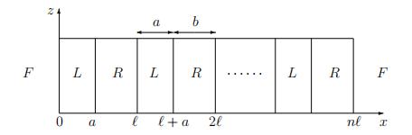
Figure 1. xz-cross section of an n-cell periodic layers (L/R)n embedded between ferromagnetic (F) semiconductors at x<0 and x>nℓ. A layer L has width a while a layer R has width b so that the periodicity ℓ=a+b.
The transmission of polarized electrons through the multilayers will be derived using the method of transfer matrix for finite periodic systems[22,23]. With the method, the wave function ψ(x1) (that is written as a wave vector) at point x1, and that at x2 are related by a transfer matrix T(x1, x2) as ψ(x1)=T(x1, x2)ψ(x2) in which the transfer matrix possesses a multiplication property as T(x1, x2)=T(x1, xi)T(xi, x2). The laws of physics, including the time reversal symmetry, that govern the multilayer and the boundary conditions satisfied by the wave function throughout the multilayer are taken into account in the transfer matrix. The physical parameters of the multilayer, such as the size and type of each layer, are also taken into account in the transfer matrix. For the periodic part within the multilayer, the transfer matrix is determined in terms of the parameters of a unit cell of the multilayer. In this case, of particular importance is to obtain the matrix elements of a unit-cell transfer matrix T(x0, x0+ℓ) (where x0 can be arbitrarily chosen, and ℓ=a+b is the periodicity of the multilayer), such as the matrix element α=T11(x0, x0+ℓ)-element and the matrix element β=T12(x0, x0+ℓ)-element of the unit cell (with the other elements may be related to them). By the multiplication property of the transfer matrix, the elements of the total transfer matrix for the complete multilayer will then be determined in terms of those matrix elements of the unit-cell transfer matrix. The wave function and the transport properties of the multilayer can be obtained[22,23] and the space-time evolution of the wave throughout the system can also be determined and studied[24,25].
To start with an example of our study, we consider a periodic n-cell multilayer (L/R)n
where L is a ferromagnetic (F) semiconductor while R is an insulator (I). We assume themultilayer to be located at 0≤x≤nℓ and embedded between ferromagnetic semiconductors at x<0 and x>nℓ as in Figure 1.
Let us consider an incoming polarized electron wave ψ(x)=exp(ikx) from the left (x<0) of the multilayer. The incoming wave may be assumed to make an angle θ to the normal (x axis) of the multilayer with k=|k|cosθ and ![]() where m is the effective mass of an electron, E is the energy, and Ve is the average sd-exchange energy in the ferromagnetic semiconductor.
where m is the effective mass of an electron, E is the energy, and Ve is the average sd-exchange energy in the ferromagnetic semiconductor. ![]() with Planck constant h. By conserving the in-plane momenta, the wave will then be transmitted through the multilayer as ψ(x)=
with Planck constant h. By conserving the in-plane momenta, the wave will then be transmitted through the multilayer as ψ(x)=![]() exp(ikx) at x>nℓ with
exp(ikx) at x>nℓ with ![]() the transmission amplitude.
the transmission amplitude.
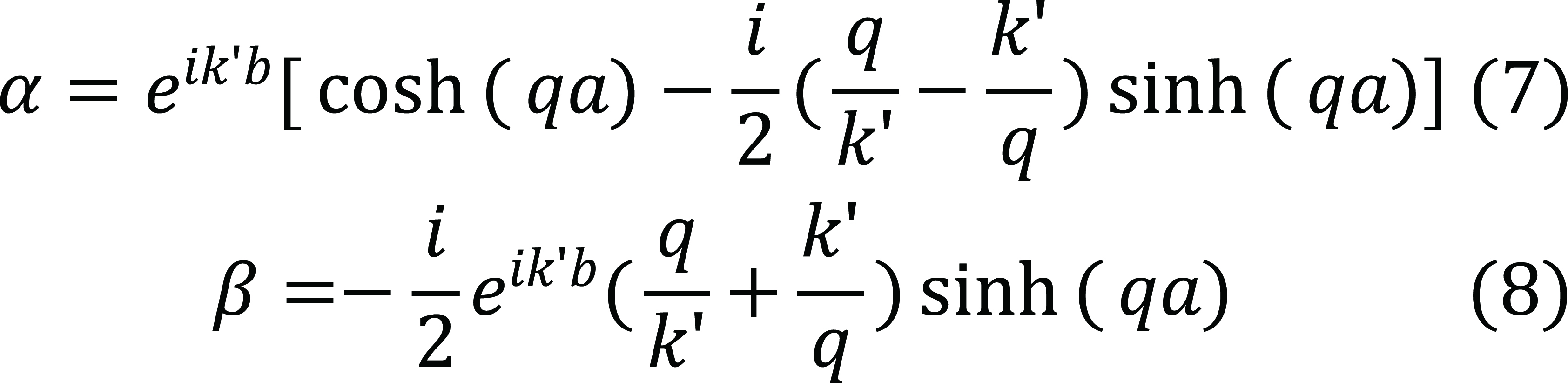
With the method of transfer matrix for finite periodic systems[22,23], the matrix elements α=T11(0, ℓ) and β=T12(0, ℓ) of the unit cell for the system considered are, respectively,
|
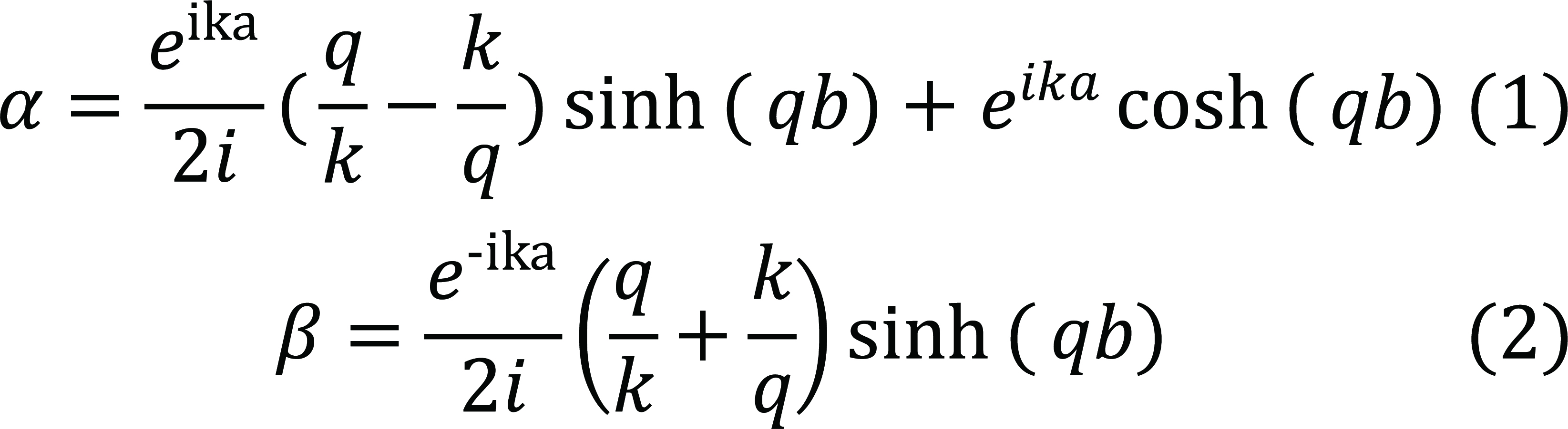
Here, ![]() where
where ![]() with mI the effective mass of an electron and VI the barrier height in the insulating layers. Furthermore, with the method of transfer matrix[22,23], the transmission amplitude
with mI the effective mass of an electron and VI the barrier height in the insulating layers. Furthermore, with the method of transfer matrix[22,23], the transmission amplitude ![]() is given by
is given by
|
Here, the matrix element αT=T11(0, nℓ)-element of the total transfer matrix of the multilayer. In this case,
|
where Un(x) are the Chebyshev polynomials of the second type[26], and αR is the real part of α. One finds the transmission coefficient cT=|![]() |2 as
|2 as
|
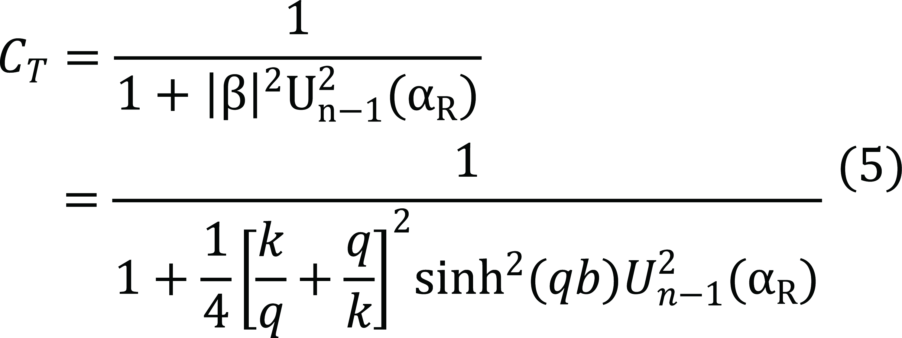
This results in transmission coefficients without a true gap as a function of energy. The transmission coefficient has resonances when Un−1(aR)=0, so that
|
with ν=0, ±1... The last expression shows that a resonance for a certain number n of
cells, can also be a resonance for other numbers of cells, such as resonances at energies Eν,n as E1,3=E2,6=E3,9, etc.
Analogously, for symmetric multilayer (L/R)nL the results for the matrix element αT
and the transmission coefficient cT are also obtained in a similar fashion (see below).
3 RESULTS AND DISCUSSION
To illustrate our results, as the first example we consider multilayer (L/R)n with ferromagnetic layer L=Ga0.73Mn0.27N that has sd-exchange energy Ve=0.23eV, and non-ferromagnetic insulating layer R=Al0.3Ga0.7As that has barrier height VI= 0.23eV.
To see an immediate effect of the exchange energy, by utilizing the properties of resonances we show in Figure 2 the transmission coefficient when the number of cells n=2, for polarized electrons (red curve with single peak) and unpolarized electrons (blue curve with four peaks). This shows the advantage of using multilayer (L/R)2 with polarized electrons as to produce precise transmission of polarized electrons with only one specific energy (red curve) with relatively small width; the width that can be made thinner by having a thicker insulating layer b for a fixed ferromagnetic layer width a (see below).
|
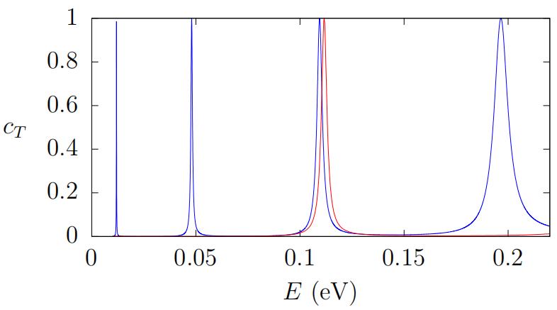
Figure 2. Transmission coefficients of polarized and unpolarized electrons of normal incidence as a function of energy E through multilayer (Ga0.73Mn0.27N/Al0.3Ga0.7As)2 (as Figure 1 with n=2). Red curve is for polarized electrons while blue curve is for unpolarized electrons. We have used m=0.2m0 with m0 the mass of free electron, Ve=0.23eV, a=100Å, b=30Å, VI=0.23eV, and mI=0.1m0 in Al0.3Ga0.7As layers.
We also show in Figure 3 transmission coefficients when a=100Å and a=200Å for fixed b=30Å, which shows the importance of using a certain width of the ferromagnetic layers in multilayer (L/R)2 when using polarized electrons such as to produce precise transmission with a specific energy (red curve). Furthermore, Figures 2 and 3 show the effect of sd-exchange as a spin-filter mechanism to transmit polarized electrons with high transmission about resonances and to suppress those others with low transmission. Therefore, with the properties of resonances, the use of multilayer with n=2 provides a simple way to obtain a spin-filter with only a small number of resonances, such as shown in Figure 3 with only a single-peaked (red curve) polarized electrons with resonance energy at E=0.1116eV when using a=100Å and b=30Å. The width about resonance can be made thinner by taking a thicker insulating width b such as b=40Å which results in the resonance energy a bit shifted to E=0.1106eV.
|

Figure 3. Transmission coefficients of polarized electrons of normal incidence as a function of energy E through multilayer (Ga0.73Mn0.27N/Al0.3Ga0.7As)2 (as Figure 1 with n=2). Red curve uses width a=100Å while blue curve uses a=200Å. Other parameters are as in Figure 2.
For a comparison, to show the energy dependence for a bigger number n of cells, we have plotted in Figure 4 the transmission coefficient for n=6 which has resonances compared to that for n=1 with much lower transmission without resonance. This shows how the number of cells n>2 can produce multiple high transmission with precise energies.
|
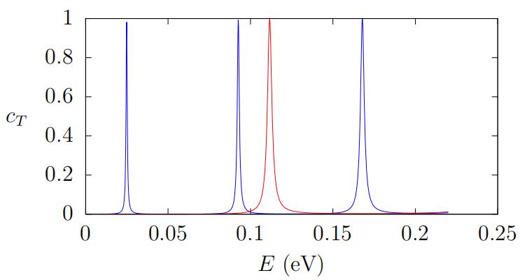
Figure 4. Transmission coefficient of polarized electrons of normal incidence as a function of energy E through multilayer (Ga0.73Mn0.27N/Al0.3Ga0.7As)n with n=1 (red curve) and n=6 (blue curve). Other parameters are as in Figure 2.
Another example, for a higher energy regime, we consider a multilayer with ferromagnetic Al0.9Fe0.1Sb as the insulating layers[17]. Figure 5 compares transmission coefficients through multilayer (Ga0.73Mn0.27N/Al0.3Ga0.7As)2 (blue curve, see also Figure 2) and multilayer (In0.92Fe0.08As/Al0.9Fe0.1Sb)2 (red curve). This indicates how the ferromagnetic insulating Al0.9Fe0.1Sb is effective as a fine-tuned spin-filter tunnel barrier for transmission of polarized electrons with specific relatively high energy.
|
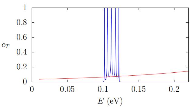
Figure 5. Transmission coefficient of polarized electrons of normal incidence as a function of energy E. Blue curve is through (Ga0.73Mn0.27N/Al0.3Ga0.7As)2 with non-ferromagnetic insulating layers (for 0<E<0.23eV) while red curve is through multilayer (In0.92Fe0.08As/Al0.9Fe0.1Sb)2 with ferromagnetic insulating layers.
Figure 6 describes transmissions through multilayer (In0.92Fe0.08As/Al0.9Fe0.1Sb)n when n=2 and n=6. Interestingly, Figures 5 and 6 show that only polarized electrons with certain energies within relatively small widths that are transmitted through the multilayers. The red curve in Figure 5 for n=2 shows a sharp peak at E=0.5024eV, while Figure 6 for n=6 (blue curve) shows sharp peaks at several energies. This indicates how the insulating ferromagnetic Al0.9Fe0.1Sb is effective as a fine-tuned spin-filter tunnel barrier as suggested in the reference[17]. Figure 6, on the other hand, shows the case of n=6, which shows how the ferromagnetic insulating Al0.9Fe0.1Sb is effective as a fine-tuned spin-filter tunnel barrier for transmission of polarized electrons of various energies (blue curve). By utilizing the properties of resonances, one may then use a multilayer with n=2 to transmit polarized electrons with a selected energy of resonance, by varying the width a of the ferromagnetic layers for fixed width b of the insulating layers, or vice versa.
|
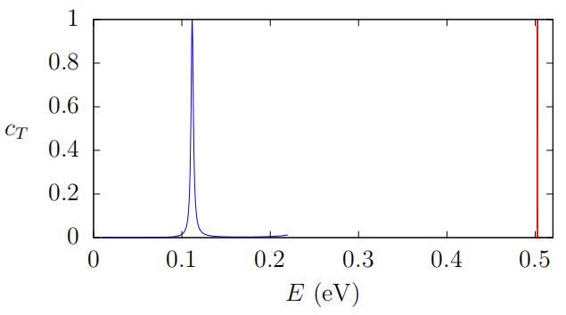
Figure 6. Transmission coefficient of polarized electrons of normal incidence as a function of energy E through multilayer (In0.92Fe0.08As/Al0.9Fe0.1Sb)6 (blue curve) when n=6, and the case of n=2 (red curve). We have used Ve=2.8eV, m=0.11m0, a=100Å, and b=30Å, mI=0.11m0, VI=1.15eV in Al0.9Fe0.1Sb layers.
Consider now multilayer (L/R)n where L is an insulator while R is ferromagnetic (F′)
semiconductor that is different than the ferromagnetic F embedding the multilayer. An
example is a multilayer with F′=Ga0.8Fe0.2N which has sd-exchange energy V′e=0.1eV[14,15], and insulating layers Al0.3Ga0.7As with barrier height VI=0.23eV. We may take the embedding semiconductors F=In0.92Fe0.08As[16]. In this case, with incomingwave number k=|k|cosθ, the wave number in F′ layers is ![]() while in the insulating (I) layers q is as before. Here we have a unit cell with the matrix elements α and β given, respectively, by
while in the insulating (I) layers q is as before. Here we have a unit cell with the matrix elements α and β given, respectively, by
|
In this case, the T11-element αT of the total transfer matrix T(0, nℓ) for the transmission amplitude ![]() is now
is now
|
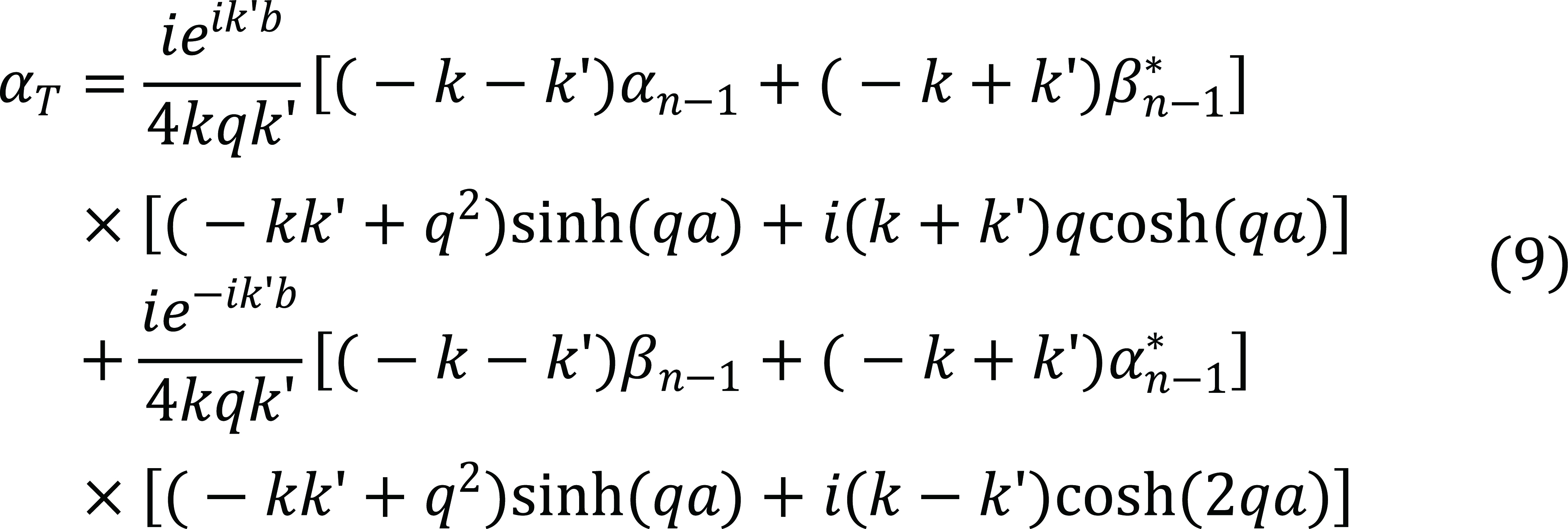
Here, we have
|
Figure 7 plots the transmission coefficient through multilayers (L/R)n for n=2 and n=4 when L is insulator Al0.3Ga0.7As, and R is ferromagnetic semiconductor F′=Ga0.8Fe0.2N where the multilayer is embedded between ferromagnetic semiconductor F=In0.92Fe0.08As.
|
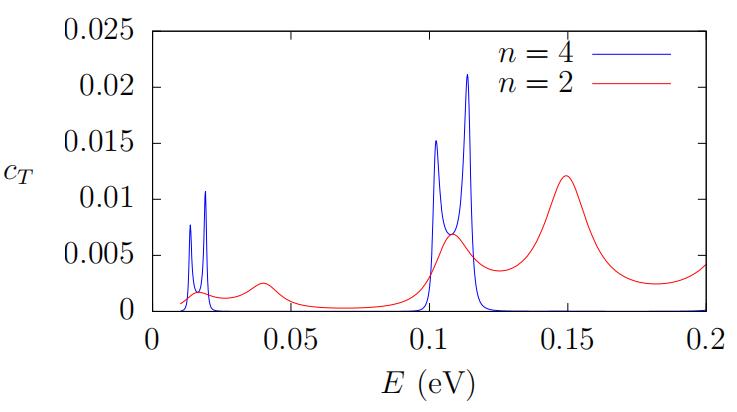
Figure 7. Transmission coefficient of polarized electrons of normal incidence as a function of energy E through multilayer (Al0.3Ga0.7As/Ga0.8Fe0.2N)n with n=2 (red curve) and n=4 (blue curve), embedded between ferromagnetic semiconductor In0.92Fe0.08As. We have used Ve=2.8eV, m=0.11m0 in F, Ve′=0.1eV, m′F=0.2m0 in F′, a=30Å, b=100Å, VI=0.23eV, and mI=0.1m0 in Al0.3Ga0.7As layers.
The figure shows relatively broaden curve with low transmissions which may not be convenient for spin-filter spintronic systems, unless low transmissions are the ones needed. The figure in general shows relatively lower transmissions compared to those in the previous cases with resonances when the ferromagnets inside the multilayers are the same as those embedding the multilayer. This shows how the use of ferromagnetic layers F′ that are different than those F embedding the multilayer may be of disadvantage to produce transmitted polarized electrons with specific energies of small widths.
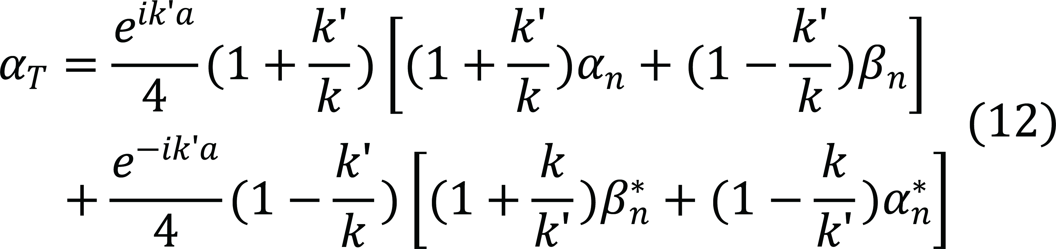
To complete our examples for comparisons we now consider symmetric multilayer (L/R)nL with L ferromagnetic semiconductors F′ different than the ferromagnetic semiconductors F embedding the multilayer. An example is multilayer with L=Ga0.8Fe0.2N, and insulator R=Al0.3Ga0.7As with barrier height VI=0.23eV, while the embedding ferromagnetic semiconductors are F=In0.92Fe0.08As. The matrix elements α and β are as Equations (1) and (2), respectively, but with k→k′. The matrix element αT=T11(0, nℓ+a) of the total transfer matrix for the transmission amplitude ![]() becomes
becomes
|
The transmission coefficient through multilayers (Ga0.8Fe0.2N/Al0.3Ga0.7As)nGa0.8Fe0.2N for n=1, 6 is shown in Figure 8. The figure shows that the use of ferromagnetic layers F′ different than those F embedding the multilayer leads to low transmission of polarized electrons as compared to those when F′=F. The figure also shows relatively lower transmissions compared to those in the previous cases.
|
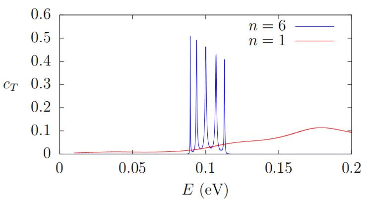
Figure 8. Transmission coefficient of polarized electrons of normal incidence as a function of energy E through multilayer (F′/I)nF′=(Ga0.8Fe0.2N/Al0.3Ga0.7As)nGa0.8Fe0.2N for n=1 (red curve) and n=6 (blue curve), embedded between semiconductors F=In0.92Fe0.08As. We have used Ve=2.8eV, m=0.11m0 in In0.92Fe0.08As, V′e=0.1eV, m′F=0.2m0 in Ga0.8Fe0.2N; a=100Å, b=30Å, VI=0.23eV, and mI=0.1m0 in Al0.3Ga0.7As layers.
4 CONCLUSION
We have calculated analytically exact transmission coefficients of polarized electrons through finite multilayered spintronics that consist of ferromagnetic semiconductors and insulating layers. Variations on the ferromagnetic semiconductors (of different sd-exchanges) and insulators of the layers allow us to study different characteristics of transmission of polarized electrons through various multilayers. By varying the number of cells and the thicknesses of the layers one can use multilayers as spin filters to select various polarized electrons with high transmissions at certain energies and suppressing the others with low transmissions. The use of ferromagnetic semiconductors with high sd-exchange energy and ferromagnetic insulating layers shows an effective way to obtain polarized electrons with selected energies within relatively small widths to be transmitted through the multilayer, so that the multilayer behaves as a spin-filter for polarized electrons with single or multiple precise energies depending on the number of cells n. This is desirable for transport of polarized electrons not only in systems of spintronics in general, but also especially important for the study of fundamental physics such as macroscopic quantum phenomena in ferromagnetic and antiferromagnetic spintronics where one uses polarized electrons with desirably precise energy to study transition of the magnetization in ferromagnetic spintronics and the Néel vector of antiferromagnetic spintronics with or without dissipation.
Acknowledgements
Not applicable.
Conflicts of Interest
The author declared no conflict of interest.
Author Contribution
Simanjuntak HP solely contributed to the manuscript and approved the final version.
References
[1] Slonczewski JC. Conductance and exchange coupling of two ferromagnets separated by a tunneling barrier. Phys Rev B, 1989; 39: 6995.[DOI]
[2] Berger L. Emission of spin waves by a magnetic multilayer traversed by a current. Phys Rev B, 1996; 54: 9353.[DOI]
[3] Slavin A, Tiberkevich V. Exitation of Spin Waves by Spin-polarized Current in Magnetic Nano-Structures. IEEE T Magn, 2008; 44: 1916-1927.[DOI]
[4] Slavin A, Tiberkevich V. Nonlinear Auto-Oscillator Theory of Microwave Generation by Spin-Polarized Current. IEEE T Magn, 2009; 45: 1875-1916.[DOI]
[5] Gomonay EV, Loktev VM. Distinctive effects of a spin-polarized current on the static and dynamic properties of an antiferromagnetic conductor. Low Temp Phys, 2008; 40: 198-206.[DOI]
[6] Gomonay O, Jungwirth T, Sinova J. Concepts of antiferromagnetic spintronics. Phys Status Solidi-R, 2017; 11: 1700022.[DOI]
[7] Umetsu N, Miura D, Sakuma A. Microscopic theory on the Gilbert damping due to spin pumping effects in the magnetic multi-layer system. J Phys Conf Ser, 2011; 266: 012084.[DOI]
[8] Munekata H, Ohno H, von Molnar S et al. Diluted magnetic III-V semiconductors. Phys Rev Lett, 1989; 63: 1849.[DOI]
[9] Ohno H, Munekata H, Penney T et al. Magnetotransport properties of p-type (In,Mn)As diluted magnetic III-V semiconductors. Phys Rev Lett, 1992; 68: 2664.[DOI]
[10] Ohno H, Shen A, Matsukura F et al. (Ga,Mn)As: A new diluted magnetic semiconductor based on GaAs. Appl Phys Lett, 1996; 69: 363-365.[DOI]
[11] Hayashi T, Tanaka M, Nishinaga T et al. (GaMn)As: GaAs-based III-V diluted magnetic semiconductors grown by molecular beam epitaxy. J Cryst Growth, 1997; 175-176: 1063-1068.[DOI]
[12] Hsu WT, Hsieh TY, Chen HF et al. Determination of s-d exchange coupling in GaMnN by time-resolved Kerr rotation spectroscopy. Phys Rev B, 2014; 90: 125205.[DOI]
[13] Adhikari R, Stefanowics W, Faina B et al. Upper bound for the s-d exchange integral in n-(Ga,Mn)N:Si from magnetotransport studies. Phys Rev B, 2015; 91: 205204.[DOI]
[14] Pacuski W, Kossacki P, Ferrand D et al. Observation of Strong-Coupling Effects in a Diluted Magnetic Semiconductor Ga1-xFexN. Phys Rev Lett, 2008; 100: 037204.[DOI]
[15] Rousset JG, Papierska J, Pacuski W et al. Relation between exciton splittings, magnetic circular dichroism, and magnetization in wurtzite Ga1-xFexN. Phys Rev B, 2013; 88: 115208.[DOI]
[16] Hai PN, Anh LD, Tanaka M. Electron effective mass in n-type electron-induced ferromagnetic semiconductor (In,Fe)As: Evidence of conduction band transport. Appl Phys Lett, 2012; 101: 252410.[DOI]
[17] Anh LD, Kaneko D, Hai PN et al. Growth and characterization of insulating ferromagnetic semiconductor (Al,Fe)Sb. Appl Phys Lett, 2015; 107: 232405.[DOI]
[18] Hirohata A, Yamada K, Nakatani Y et al. Review on spintronics: Pinciples and device applications. J Magn Magn Mater, 2020; 509: 166711.[DOI]
[19] Simanjuntak HP. Transitions of the magnetization in the presence of a polarized current. J Magn Magn Mater, 2018; 468: 185-187.[DOI]
[20] Simanjuntak HP. Macroscopic quantum phenomena in spintronics. Nova Science Publishers: New York, USA, 2019.
[21] Simanjuntak HP. Transitions of the Néel vector in spintronics. J Magn Magn Mater, 2019; 482: 84-87.[DOI]
[22] Pereyra P, Castillo E. Theory of finite periodic systems: General expansions and various simple and illustrative examples. Phys Rev B, 2002; 65: 205120.[DOI]
[23] Pereyra P. The Transfer Matrix Method and the Theory of Finite Periodic Systems. From Heterostructures to Superlattices. Phys Status Solidi B, 2022; 259: 2100405.[DOI]
[24] Simanjuntak HP, Pereyra P. Evolution and tunneling time of electron wave packets through a superlattice. Phys Rev B, 2003; 67: 045301.[DOI]
[25] Simanjuntak HP, Pereyra P. Space-time evolution of wave packets through superlattices. Phys Status Solidi, 2005; 2: 3108-3113.[DOI]
[26] Gradshteyn IS, Ryzhik IM. Table of Integrals, Series, and Products, 5th ed. Academic Press: San Diego, USA, 1994.
Copyright © 2024 The Author(s). This open-access article is licensed under a Creative Commons Attribution 4.0 International License (https://creativecommons.org/licenses/by/4.0), which permits unrestricted use, sharing, adaptation, distribution, and reproduction in any medium, provided the original work is properly cited.


