Calculation of the Modulus of Meshing of Spur Gears According to the Wear Resistance of Gear Teeth
Amirkul Irgashev1*
1Service Delivery Techniques, Tashkent State Technical University, Tashkent, Uzbekistan
*Correspondence to: Amirkul Irgashev, PhD, Professor, Service Delivery Techniques, Tashkent State Technical University, 2 Universitet Ko'chasi, Tashkent 100095, Uzbekistan; Email: irgashevamirkul@mail.ru
Abstract
Objective: The aim of the article is to develop a method for calculating the mesh modulus of a gear while considering the wear rate of the gear teeth.
Methods: Dependences for calculating the meshing modulus under rolling and rolling with slippage conditions are proposed.
Results: The analytical dependencies obtained allow the calculation of the wear rate of gear teeth, with or without abrasive particles in the unit oil, taking into account the geometrical and kinematic parameters of the gear meshing, mechanical properties of the material of gear wheels, strength, concentration and size of abrasive particles.
Conclusion: The method of calculation of the meshing modulus provided differs from the conventional method by taking into account the wear rate of gear teeth, when rolling or rolling with slippage occurs between them.
Keywords: meshing modulus, closed gear, rolling, rolling with slippage, abrasive particles, abrasive particles compressive strength, crushing, pure oil, hardness of gear material, bending stress, yield strength of material
1 INTRODUCTION
The main cause of pinion failure is pitting on the surface of the rolling zone of the gear teeth caused by fatigue phenomena, which are related to the contact durability of the gear material. The key point in ensuring the strength of the teeth is therefore the contact stresses that arise in the rolling zone of the gear teeth, i.e. in the contact zone of the initial circles of the gear meshing[1]. During meshing, tooth contact occurs at the head and foot of the gear teeth, which simultaneously roll and slide, and their strength is described by the slip coefficient. It has been found that with the distance of the meshing point from the initial circle towards the head and foot of the teeth, the slip coefficient increases, thereby increasing wear of the gear teeth[2].
Studies carried out on the definition of wear resistance of gear teeth of the closed gears, working at presence and absence in oil of abrasive particles, have determined that the head and foot of teeth are exposed to maximum wear, and in most cases on these reasons the gears are rejected[3,4]. Therefore, in the design calculations to determine the gear mesh modulus, in addition to the complex factors, characterising the strength and geometrical parameters, the factors affecting the wear resistance of the gear should also be considered.
The purpose of this work is to substantiate the meshing modulus of closed gears, depending on the complexity of parameters, in the presence and absence of abrasive particles in the oil of the unit.
2 MATERIALS AND METHODS
To determine the meshing modulus of the gears, the ratio of the gear tooth length L to the coefficient was used, which depends on the mode of loading. Based on data indicated in the literature for heavily loaded precision gears, shafts, bearings and housings of increased precision, the range of ψm=45...30[1] was determined, wherein the meshing modulus is defined:
|
Methods of calculating the mesh modulus of gears under lubricated conditions and in the case of slippage need to be considered when abrasive particles are involved in the wear process.
Abrasive particles, located in the wedge-shaped gap between the gear teeth, under the influence of friction forces move toward the contact zone. As a result, they are subjected to all increasing normal loads during movement, as their penetration depth into the friction surfaces of the gear teeth increases. Depending on the value of this parameter, abrasive particles can cause elastic-plastic deformation or microcutting of the friction surface[5-9]. When normal pressure acting on abrasive particles reaches the strength limit, these particles are squeezed and the squeezing of the abrasive particles takes place in the wedge gap between the gear teeth, without reaching their contact zone[5,10]. In this case, the abrasive particles in the wedge gap between the gear teeth deform the same volume of metal repeatedly until they are destroyed, as fatigue wear of the material occurs on the gear teeth.
In the proposed method, the modulus of engagement of a closed gear is calculated taking into account the degree of activity of the abrasive particles when operating in oil. It is accepted that abrasive particles in contact with the friction surface, subject to normal loads and involved in the wear process, are considered active abrasive particles. The presence and advancement of abrasive particles in the wedge-shaped gap of gear units in the slippage rolling zone perceive a gradually increasing normal load, leading to an increase in the friction force between the abrasive particle and the friction surface. Under the influence of frictional force, the abrasive particle moves towards the contact zone of the rubbing surfaces. This may reach a point where the compression stress exceeds the strength of the abrasive particle and crushing occurs.
According to Kragelsky and Alisin[5], the crushing process did not reach the tooth contact zone in sevenfold repetition, so that the size of the crushed abrasive particles becomes smaller than the sum of the roughness height and thickness of the oil film. Abrasive particles crushed to this degree have no force interaction with friction surfaces and cause no wear. Such particles are called passive abrasive particles; crushed abrasive particles do not cause wear. Based on the above-mentioned wear process of gear teeth, we can assume that, firstly, abrasive wear with active abrasive particles occurs, in which the gear teeth are not mutually in contact; i.e. contact of friction surfaces occurs through abrasive particles located in the wedge-shaped gap.
After the abrasive particles have been crushed, the wear process on the tooth surfaces occurs in their absence, as a result of the interaction of the roughness protrusions of the mutually contacting teeth. Thus, the total wear rate of a tooth therefore consists of the sum of the rate of wear in which the abrasive particles are actively involved and the rate of deformation of the roughness protrusions located on the tooth contact surfaces[2].
3 RESULTS AND DISCUSSION
The total wear rate of gear teeth is calculated by the following formula:
|
Where γa, γd: The wear rates of gear teeth with active abrasive particles and as a result of tooth surface deformation by roughness projections, located on the contact surfaces, and the value of total linear wear; U, Ua and Ud: Wear with active and passive participation of abrasive particles; T: Full-service life of the gear on the maximum wear of the teeth. By the results of the experimental studies carried out in this direction, it was established that the general size of the linear wear of gear teeth consists of the wear, with active participation of abrasive particles, which has a value of approximately 80% of the general wear of the teeth, as a result of the wear caused by roughness, on the contact surfaces of the teeth, which accounts for approximately 20% from the general linear wear[11]. The maximum allowable value of total tooth wear is 25% of the tooth thickness on the initial circumference of the gear[12].
The equation to calculate the total wear rate within its components as a function of the gear modulus was solved to obtain the dependence[11]:
|
Where Hsh: Hardness of the gear material, MPa; zk: Number of teeth of the driven gear; σa: Compressive strength of abrasive particles, MPa; εk: Concentration of abrasive particles in the unit oil, %; γm, γa : Densities of oil and abrasive particles, t/m3; dcr: Average size of abrasive particles involved in the wear process, m; kv: Coefficient, taking into account the shape of abrasive particles; nsh: Rotation frequency of the driving (driven) gear, s-1; i: Gear ratio; с: The coefficient of deformation of friction surfaces; Еpr: The reduced modulus of elasticity of gear material, МPа; Т: The limit of service life, hour; npsh: The number of cycles resulting in the destruction of deformed friction surface of gear (wheel) tooth; ψ: The slip coefficient of gear teeth; Gsh: The hardness ratio of gear material and the strength of abrasive particles.
Equation (1) is to calculate the modulus of gearing consisting of two components. By opening the bracket and simplifying each term of the equation, the equation for determining the total meshing modulus in the presence of slippage between the gear teeth, allows for the calculation of the components of the total meshing modulus: in the presence of abrasive particles in the unit oil, after crushing the abrasive particles, the surface deformation of the teeth contact zone with the projections of the roughness is taken into account.
Then, the equation obtained to calculate the meshing modulus in the presence of active abrasive particles taken together with oil and slippage between the teeth is equal:
|
Thus, from the obtained Equation (2), we can conclude that increasing the hardness of the gear material, the number of teeth of the driven gear, the coefficient that takes into account the ratio of hardness of the gear material, and the strength of abrasive particles, will result in the decrease in the gear meshing module. With increasing strength, concentration, and size of abrasive particles in the oil of the unit, the tooth slip ratio, the gear ratio, gear rotation frequency, and the service life of the gearing, the engagement modulus increases.
The coefficient takes into account the ratio of the hardness of the gear material and the strength of the abrasive particle depends on the hardness of the gear material and the compressive strength of the abrasive particles[2,11]:
|
Table 1 shows the calculation results for the coefficient that takes into account the ratio of hardness of the gear material and the strength of abrasive particles. This coefficient decreases by 1.7-1.9 times with an increase in the hardness of the gear material within the range from 200 to 700MPa. Increasing the compressive strength of abrasive particles from 100MPa to 600MPa leads to an increase in the coefficient in the range of 1.6-1.8 times.
Table 1. Calculation Results of the Coefficient That Takes into Account the Ratio of Hardness of the Gear Material and the Strength of Abrasive Particles, Gsh
Hsh, MPa |
200 |
300 |
400 |
500 |
600 |
700 |
|
σa, MPa |
Ratio of hardness of gear material to the strength of abrasive particles, Gsh |
||||||
100 |
4.328 |
3.723 |
3.299 |
2.989 |
2.751 |
2.562 |
|
200 |
4.000 |
4.680 |
4.328 |
4.000 |
3.723 |
3.493 |
|
300 |
4.899 |
4.000 |
4.763 |
4.568 |
4.328 |
4.104 |
|
400 |
5.657 |
4.619 |
4.000 |
4.778 |
4.680 |
4.509 |
|
500 |
6.325 |
5.164 |
4.472 |
4.000 |
4.769 |
4.736 |
|
600 |
6.928 |
5.659 |
4.899 |
4.382 |
4.000 |
4.769 |
|
Coefficient of relative elongation of the gear material,ψush |
|||||||
ψush |
5.5 |
5.0 |
4.5 |
4.0 |
3.5 |
3.0 |
|
Numbers of deformation cycles leading to the destruction of the deformed friction surface of the drive pinion, nrsh |
|||||||
nrsh |
9.172 |
8.103 |
7.066 |
6.063 |
5.097 |
4.171 |
|
The number of deformation cycles, resulting in failure of the deformed friction surface of the pinion tooth, depends on material hardness and is defined according to research by Kragelsky and Alisin[5], by the equation npsh=ψusht, where ψush is the elongation factor of pinion material, %; t is the material friction fatigue factor, for steels it is taken equal to t=1.3[5]. As the hardness of the gear material increases, this number of cycles decreases (Table 1), which is associated with a decrease in the coefficient of relative elongation of the material of the gear pinion, resulting in a decrease in the coefficient of relative elongation of the material gear in 1.83 times. As a result, this is associated with an increase in brittleness of the material of the pinion. Increasing the hardness of the material from 200 to 700MPa, the number of deformation cycles leading to the destruction of the deformed friction surface decreases by 1.45 times with the hardness of the gear material of 200MPa and 1.60 times with a hardness of 700MPa.
Thus, increasing the hardness of the pinion material leads to a decrease in the ratio of the hardness of the pinion material to the strength of the abrasive particles, with the value of this factor increasing as the strength increases.
Calculation of the value of the slip coefficient of gear teeth included in Equation (2) was carried out by the dependence[11].
|
Where zsh: Number of teeth of the driving gear; α: Meshing angle; k: Coefficient, taking into account the height of the head and foot of the teeth, which have the same value for gears without offset. In the formula for calculating the slip coefficient, the value of k shows the ratio of the accepted distance from the initial circle of the driving gear towards the circles of projections and troughs of the meshing gears on the height of the head or foot of the teeth. If the sign before the term 4k2 in the Equation (4) to calculate the slip coefficient of the gears is positive, then the Equation (4) refers to the head, while if negative, it refers to the feet of the teeth.
The results of calculating the slip coefficient of the gears teeth are shown in Table 2 for different values of the head and foot of the teeth height factor k and the number of teeth of the drive pinion.
Table 2. Change in the Coefficient Considering the Relative Slippage of the Gear Teeth Depending on the Tooth Height Factor k
k |
0.000 |
0.167 |
0.333 |
0.500 |
0.667 |
0.833 |
1.000 |
zsh |
Slip coefficient of gear teeth for the head |
||||||
11 |
0.000 |
0.873 |
1.645 |
2.331 |
2.967 |
3.559 |
4.115 |
15 |
0.000 |
0.908 |
1.706 |
2.439 |
3.125 |
3.759 |
4.367 |
19 |
0.000 |
0.920 |
1.748 |
2.513 |
3.236 |
3.906 |
4.566 |
23 |
0.000 |
0.929 |
1.776 |
2,571 |
3.311 |
4.016 |
4.695 |
27 |
0.000 |
0.936 |
1.795 |
2.611 |
3.378 |
4.115 |
4.808 |
31 |
0.000 |
0.940 |
1.812 |
2.639 |
3.425 |
4.184 |
4.902 |
zsh |
Slip coefficient of the gear teeth for the foot |
||||||
11 |
0.000 |
0.849 |
1.565 |
2.169 |
2.695 |
3.165 |
3.597 |
15 |
0.000 |
0.889 |
1.642 |
2.309 |
2.907 |
3.448 |
3.937 |
19 |
0.000 |
0.905 |
1.692 |
2.404 |
2.865 |
3.636 |
4.184 |
23 |
0.000 |
0.917 |
1.730 |
2.469 |
3.155 |
3.788 |
4.386 |
27 |
0.000 |
0.923 |
1.757 |
2.525 |
3.236 |
3.891 |
4.525 |
31 |
0.000 |
0.927 |
1.776 |
2.564 |
3.300 |
3.984 |
4.651 |
As can be seen from the results of the calculations given in Table 2, the slip coefficient increases as the value of k increases from 0 to 1 and the number of teeth of the drive gear zsh. Thus, at a value of k=1 and zsh=11, the slip coefficient of the teeth of the gears is 4.115 for the tooth head and 3.597 for the teeth leg. The slip coefficient of the tooth head is 12.59% higher than that of the tooth stalk. At a value of k=1 and zsh=31, the slip coefficient of the gear teeth is 4.902 for the tooth head and 4.651 for the foot of the teeth. The slip coefficient of the tooth head is 5.12% higher than that of the tooth stalk.
As the number of teeth in the pinion increases from zsh=11 to zsh=31, the slip coefficient of the teeth head increases by 16.05% and of the foot by 22.66%. Thus, it is necessary to design the gears with a smaller number of teeth for the drive gear in order to reduce the slip coefficient and increase the wear resistance of the gear teeth.
Figure 1 shows the results of calculating the meshing modulus of a gear set at rolling with slip and at the presence of abrasive particles with a maximum concentration of 1.3%, accumulated during the operation of the unit[2] according to the following initial data: εk=1.3%; i=2; Hsh=200; 300; 400; 500; 600; 700MPa; Gsh=4.899; 4.000; 4.763; 4.568; 4.328; 4.104; γa=2.1t/m3; γm=0.91t/m3; zsh=19; nrsh=9.172; 8.103; 7.066; 6.063; 5.097; 4.171; dcr=0.0115; nsh=0.5 s-1; 1.0 s-1; 1.5 s-1; 2.0 s-1; 2.5 s-1; 3.0 s-1; k=0.833; kv=0.9; ψ=3.906; ψm=35; T=10,000; 7,500; 5,000h.
|
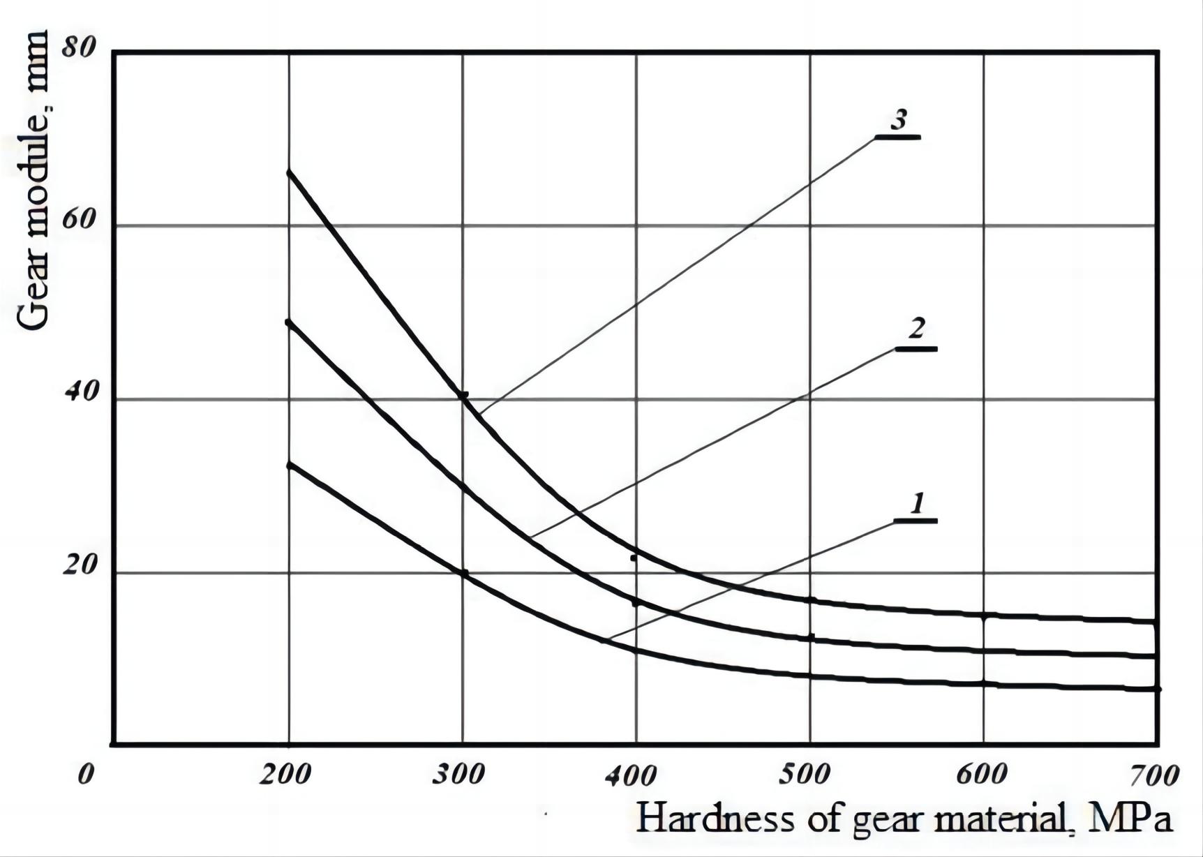
Figure 1. Change in engagement modulus depending on the hardness of the material of the pinion at the service life of the pinion: 1-T=5,000h; 2-T=7,500 h; 3-T=10,000h.
The obtained graphical dependencies show that increasing the hardness of the material of the driving gear leads to a decrease in the meshing modulus, with a service life of 5,000h by 71.43%, 7,500h by 79.59%, and 10,000h by 77.27%. This is because increasing the hardness of the material in the pinion is associated with a decrease in the linear wear of the gear teeth.
Figure 2 shows graphs of changes in gearing modulus, which depends on the concentration of abrasive particles in the oil of the machine. The calculation results show that increasing the concentration of abrasive particles from 0.5% to 3.0% of the meshing modulus ensures the serviceability of the tooth gear for the set service life of the driving gear 10,000h. The size of abrasive particles in the oil of the unit causes an increase in the meshing modulus, with the sizes of abrasive particles dcr=0.0040mm, dcr=0.0080mm and dcr=0.0115mm, in average by 98.25%;
|
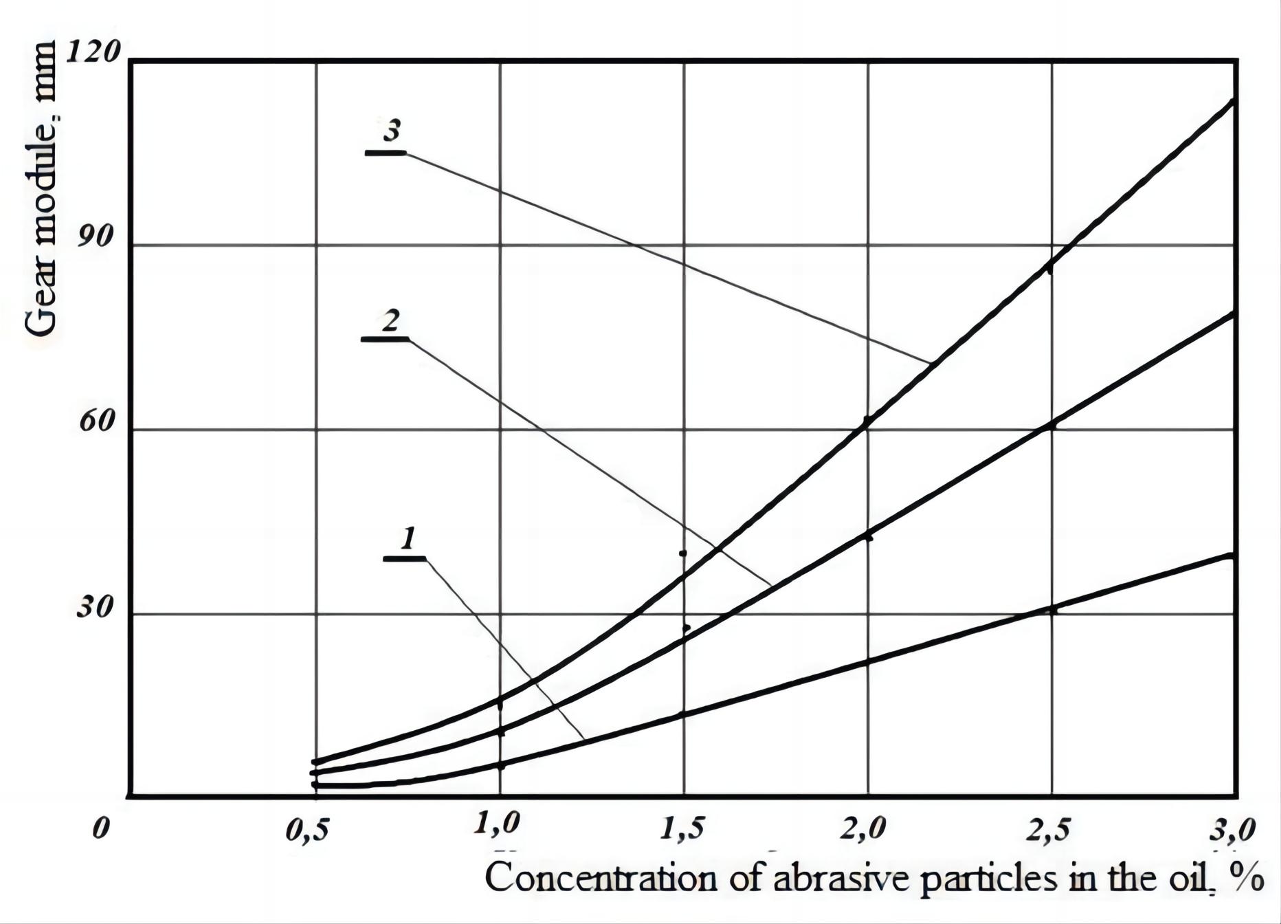
Figure 2. Change in the meshing modulus depending on the concentration of abrasive particles in the oil of the unit when the hardness of the driving gear is 400MPa and the size of abrasive particles: 1-dcr=0.0040 mm; 2-dcr=0.0080mm; 3-dcr=0.0115mm.
The modulus of engagement of gear teeth after the crushing of abrasive particles in the area in the wedge-shaped gap was calculated taking into account the fatigue of the gear material in rolling friction with slip, as the contact surfaces of the teeth are deformed by roughness projections[2]. This condition of friction is equivalent to the work of closed gear transmission on a stationary unit in clean oil, i.e. in the absence of abrasive particles in the unit. The dependence[9] was obtained to calculate the mesh modulus, taking into account the length of the gear teeth, the ultimate linear wear of the teeth, and the deformation characteristics of the gear material:
|
Where θsh is the elastic constant of the pinion material, 1/MPa; Epr is the reduced modulus of elasticity of the pinion material, MPa; c is the deformation factor; zk is the number of teeth of the driven pinion; σtsh is the yield strength of the driven pinion material, MPa. To calculate the modulus of meshing, the following input data were adopted: θsh=0.423×10⁻⁶ 1/MPa; c=3; Epr=215,000MPa; σtsh=120MPa; 180MPa; 240MPa; 300MPa; 360MPa; 420MPa; i=2.0; U=0.5mm; nrsh=9.172; 8.103; 7.066; 6.063; 5.097; 4.171; ψ=3.906; ψm=35; nsh=0.5 s-1; 1.0 s-1; 1.5 s-1; 2.0 s-1; 2.5 s-1; 3.0 s-1; zk=38; T=5,000h; 7,500h; 10,000h; U=0.5mm; i=2. σiz=250MPa; 275MPa; 300MPa; 325MPa; 350MPa; 375MPa.
Figure 3 shows the dependence of the change in modulus of engagement of a fixed gear on the bending stress at the values of linear wear of teeth on the thickness U=0.167mm, U=0.333mm, and U=0.500mm. From the obtained dependencies, the value of the gear module increases with an increase in bending stress in the meshing, since the increase in bending stress causes an increase in the amount of wear on the teeth of gears. Increasing the yield strength of the material of the pinion from 120MPa to 420MPa, the value of linear wear was U=0.167mm, U=0.333mm, and U=0.500mm, and the increase in meshing module does not depend on the linear wear on the thickness of teeth.
|
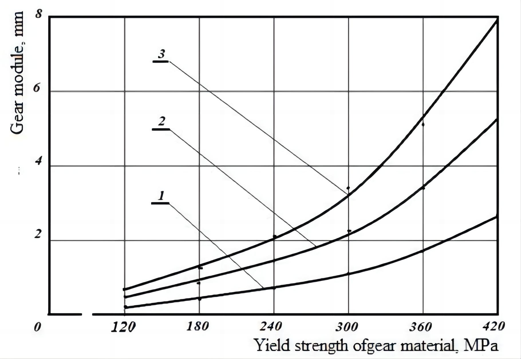
Figure 3. Change in the meshing modulus as a function of the yield strength of the material of the pinion at the value of wear of the tooth of the pinion: 1-U=0.167mm; 2-U=0.333mm; 3-U=0.500mm.
Figure 4 shows the variation of the bending stresses generated on the teeth of the meshing pinion by the meshing module driving the pinion from 250 to 375MPa at frequency of rotation.
|
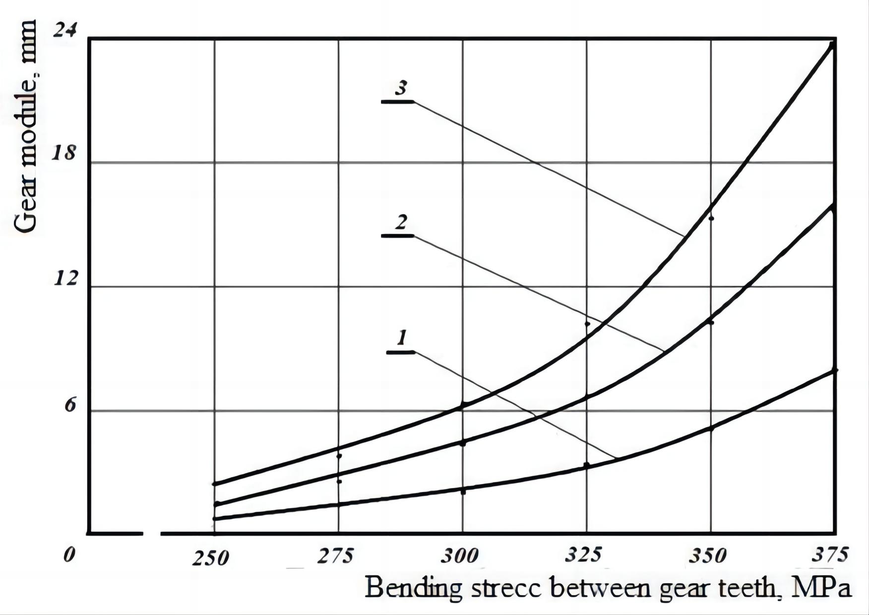
Figure 4. Change in meshing modulus depending on the bending stress in the gearing at speeds of driving gears: 1-nsh=0.5 s-1; 2-nsh=1.0 s-1; 3-nsh=1.5 s-1.
Drive pinion nsh=0.5 s-1; nsh=1.0 s-1 and nsh=1.5 s-1. It is found that as the bending stress between the teeth of the gears of the meshing module increases, the average increase is 89.88%, regardless of the rotation frequency of the dominant gear.
4 CONCLUSION
Thus, on the basis of the theoretical studies, we can draw the following conclusions.
1. The ratio of the hardness of pinion material to the strength of abrasive particles decreases by an average of 1.453-1.689 times as the hardness of pinion material increases from 200 to 700MPa, while the strength of abrasive particles increases from 100 to 600MPa, leading to an increase in the ratio of hardness of pinion material to the strength of abrasive particles in the range of 1.600-1.861 times. The increase in the hardness of the material of the driving gear from 200MPa to 700MPa leads to a decrease in the number of deformation cycles, causing the destruction of the deformed surface friction of the driving gear on average 2.20 times, which is associated with the embrittlement of the material of the driving gear on increasing their hardness.
2. The increase in the coefficient of tooth height and the number of teeth of the driving gear leads to an increase in the slip coefficient between the meshing teeth of the gears, and increasing the coefficient of tooth height from 0 to 1 the slip coefficient of the gear teeth of the tooth head increases by 4.71 times, when the number of teeth of the driving gear is 11, by 5.21 times when the number of teeth of the driving gear is 31, by 4.24 times, when the number of teeth of the driving gear is 11, and by 5.02 when the number of teeth of the driving gear is 31.
3. In the presence of abrasive particles in the oil of the unit, increasing the hardness of the material of the driving gear from 200 to 700MPa leads to a decrease in the meshing module in the service life of the driving gear: 5,000h by 4.4 times, 7,500h by 4.7 times, 10,000h by 4.8 times, when the oil in the unit contains abrasive particles concentration 1.3% in size 0.0115mm. Increasing the concentration of abrasive particles in the aggregate oil from 0.5 to 3.0% leads to an increase in meshing modulus, which increases 21.0 times when the average size of the abrasive particles in the oil is: 0.0040mm; 26.7 times for 0.0080mm; and 18.8 times for 0.0115mm.
4. In the absence of abrasive particles in the oil of the unit, as the yield strength of the material increases from 120 to 420MPa gear module, the linear wear of the pinion increases by 11.5 times at U=0.167mm, 12.1 times at U=0.333mm, and 12.8 times at U=0.500mm. Increasing the bending stress on the teeth of meshing gears from 250 to 375MPa leads to an increase in modulus of engagement at a frequency of rotation of the driving gear: nsh=0.5 s-1 at 9.4 times; nsh=1.0 s-1 at 9.9 times; nsh=1.5 s-1 at 11.3 times.
5. The meshing modulus calculated at the presence of abrasive particles in the unit's oil with the initial data of εk=1.3%; Hsh=200MPa; Gsh=4.899; zsh=19; nrsh=9.172; dcr=0.0115m; nsh=0.5 s-1; ψ=3.906; T=10,000h is 21.86mm, which is 89.61% of the total meshing modulus, and in clean oil at 1/MPa; Epr=215,000MPa; σtsh=120MPa; i=2.0; U=0.5mm; nrsh=9.172; ψ=3.906; nsh=0.5 s-1; zk=38; T=10,000h; U=0.5mm; i=2; σiz=250MPa is 2.534mm, which is 10.39% of the total hook module and equals to 24.394mm.
Acknowledgements
Not applicable.
Conflicts of Interest
The author declared no conflict of interest.
Author Contribution
Irgashev A solely contributed to the manuscript and approved the final version.
References
[1] Gorlenko OA, Makarov GN, Shnyrikov IO. Increasing the contact endurance of the teeth of spur gearings. Sci Tech Prod J, 2014; 6: 31-36.
[2] Irgashev A. Methodological bases of increasing wear resistance of gears of heavy loaded gear transmissions of machine units [doctors’ thesis]. Tashkent, Uzbekistan: Tashkent State Technical University; 2005.
[3] Irgashev BA, Irgashev AI. Forecasting the consumption of spare parts in machines based on the content of wear particles in oil. J Frict Wear, 2015; 36: 441-447. DOI: 10.3103/S1068366615050062
[4] Irgashev A, Mirzaev NN, Irgashev DA. Assessment of wear of machine unit parts by concentrations of wear products in oil: Monograph. Tashkent State Technical University: Tashkent, Uzbekistan, 2012.
[5] Kragelsky IV, Alisin VV. Friction, wear and lubrication: Handbook. Elsevier: Berkeley, USA, 1978.
[6] Shaabidov SA, Irgashev A, Mirzaev KK. Increasing operational properties of the surface layers of machine parts: Monograph. Tashkent State Technical University: Tashkent, Uzbekistan, 2012.
[7] Dubovik EA. Features of wear of gear transmissions. Sci Tech Prod J, 2015; 3: 18-25.
[8] Nefedov AV. Peculiarities of abrasion of gear wheels and worms in closed gears. Sci Tech Prod J, 2012; 1: 27-32.
[9] Irgashev A, Irgashev BA. Wear resistance of gears: Monograph. Tashkent State Technical University: Tashkent, Uzbekistan, 2013.
[10] Irgashev AI, Mirzaev KK, Irgashev BA. Increasing the wear resistance of gears: Monograph. Tashkent State Technical University: Tashkent, Uzbekistan, 2015.
[11] Report on “Development of scientific foundations to improve the wear resistance of gears of mobile machinery and industrial equipment units (final)”. Tashkent State Technical University: Tashkent, Uzbekistan, 2016.
[12] Control of the technical condition of tractor parts in the repair: Handbook, 2nd ed. Kolos: Moscow, Russia, 1973.
Copyright ©2023 The Author(s). This open-access article is licensed under a Creative Commons Attribution 4.0 International License (https://creativecommons.org/licenses/by/4.0), which permits unrestricted use, sharing, adaptation, distribution, and reproduction in any medium, provided the original work is properly cited.


