Carbon-based Perovskite Solar Cells: From Current Fabrication Methodologies to Their Future Commercialization at Low Cost
Ibrahim Albrahee1, Yang Li2*, Guichuan Xing3
2Bingtuan Energy Development Institute, Shihezi University, Shihezi, Xinjiang Uygur Autonomous Region, China
3Joint Key Laboratory of the Ministry of Education, Institute of Applied Physics and Materials Engineering, University of Macau, Macao SAR, China
*Correspondence to: Yang Li, PhD, Associate Professor, Bingtuan Energy Development Institute, Shihezi University, No. 280 Beisi Road, Shihezi, 832000, Xinjiang Uygur Autonomous Region, China; Email: yang2022@shzu.edu.cn
DOI: 10.53964/id.2025001
Abstract
Carbon electrodes are increasingly recognized as a cost-effective, environmentally friendly, durable, and scalable alternative to metal electrodes in perovskite solar cells (PSCs). This review focuses on carbon-based PSCs (C-PSCs), specifically examining their stability and efficiency through the innovative use of interfacial engineering. For efficiency enhancement, the review highlights recent advancements in C-PSCs fabrication techniques. Additionally, various approaches for producing C-PSCs with large active areas are summarized. The review concludes by discussing current challenges and potential opportunities for advancing high-performance C-PSCs. This comprehensive study aims to offer a detailed understanding of the progress in C-PSCs, illuminate the evolving landscape of renewable energy technologies, and foster the development of further breakthroughs in the field.
Keywords: carbon-based perovskite solar cells, efficiency, stability, fabrication technologies
1 INTRODUCTION
Perovskite solar cells (PSCs) have now achieved power conversion efficiencies (PCEs) comparable to those of conventional crystalline silicon solar cells[1-4]. A key objective in advancing PSC technology is to further reduce production costs while enhancing the long-term stability and reliability of these devices[5,6]. Traditional organic hole transport layers (HTLs), such as spiro-OMeTAD, and metal electrodes (e.g., gold (Au) or silver(Ag)), contribute significantly to higher manufacturing costs and device instability. This instability arises due to the hygroscopic nature of salts in HTLs and the corrosion of metal electrodes by halogen species[7-11]. To overcome these challenges, researchers have proposed simplified device architectures that replace HTLs and metal electrodes with carbon-based electrodes. Carbon materials, known for their chemical inertness, offer multiple advantages, including low cost, high stability, hydrophobicity, and excellent electrical conductivity[12-14]. Consequently, carbon-based PSCs (C-PSCs) without HTLs are emerging as promising candidates for commercial applications[15-23]. These carbon electrodes (CEs) enable the use of more affordable, eco-friendly, and widely available materials, as opposed to precious metal electrodes. This article will provide an in-depth examination of the advantages of carbon-based electrodes over traditional noble metal counterparts.
Carbon-based materials with pronounced hydrophobic properties play a critical role in enhancing the stability of PSCs. Consequently, the incorporation of CEs significantly reduces production costs while simultaneously addressing the stability challenges associated with-PSCs[24]. The main sources for carbon paste electrodes (CPE) include materials such as graphite, carbon black[25-30], carbon nanotubes (CNTs)[31,32], and biomassderived carbon[33,34]. with specific examples like spongy carbon[35], candle soot[36], aloe vera carbon[33], and coal powder[34]. Recent research has shown the promising potential of carbon-based materials in energy generation applications. For example, Liu et al.[37] demonstrated that plasma-treated carbon nanoparticles can effectively generate electricity, while Zhou and co-workers found that printable carbon black can be utilized in advanced energy technologies[38], highlighting the pivotal role of carbon materials in energy conversion. Among these materials, two-dimensional (2D) carbon structures, such as graphene, graphene oxide (GO), and reduced graphene oxide, hold significant promise in solar energy devices due to their continually improving output power and energy conversion efficiency. The integration of these materials into C-PSCs can lead to substantial improvements in performance and adaptability to various environmental conditions. Flexible devices made from 2D carbon materials offer the advantage of adapting to different environments while maintaining excellent power output, making them a promising solution for self-powered systems in future applications, including sensors and external power sources. Graphene in particular has emerged as a standout material for enhancing the electrical performance and stability of C-PSCs. Its unique two-dimensional structure, formed through the sp2 hybridization of carbon atoms, endows graphene with remarkable properties, including high electron mobility, superior mechanical strength, and a large specific surface area. When assembled into three-dimensional structures like films or foams, graphene enhances electronic transport and improves connectivity between layers in solar cells. Additionally, chemical modifications to graphene, such as the introduction of functional groups or structural defects, provide opportunities to further enhance the overall performance of these cells. Therefore, the incorporation of 2D carbon materials, especially graphene, into carbon-based perovskite solar cells represents a promising step toward improving the efficiency, adaptability, and versatility of future solar energy systems[39].
Despite these advancements, HTL-free C-PSCs are still affected by a high degree of unwanted charge recombination, primarily due to poor contact between the perovskite layer and the CE, as well as limitations in fabrication techniques. The inefficient contact at the perovskite/CPE interface is typically identified as the key factor contributing to reduced device current[14]. Therefore, applying interfacial engineering strategies is essential to improve the contact between the perovskite and the CPE, thereby minimizing charge recombination and boosting the performance of C-PSCs. This article provides an in-depth review of these interfacial engineering techniques. Carbon stands out as the ideal choice for counter electrodes in PSCs due to its abundance, tunable structural properties, chemical stability, low cost, water resistance, high carrier mobility (μcm), and its resistance to ion migration from perovskites[40-44]. The use of CEs has the potential to significantly reduce manufacturing costs, simplify fabrication processes, enhance device stability, and ultimately facilitate the large-scale commercialization of C-PSCs. It is therefore critical to evaluate recent advancements in C-PSCs to ensure improved efficiency and guide future research efforts. This review begins by addressing the environmental and economic considerations associated with C-PSCs, followed by an analysis of the interfacial structures and fabrication processes involved in their production. The review then systematically categorizes and contrasts strategies aimed at enhancing the interaction between CPEs and the perovskite layer, as well as improving the overall efficiency of C-PSCs. These strategies include the refinement of fabrication techniques, interface engineering, and the optimization of CEs. Finally, the analysis provides an assessment of the current challenges and potential opportunities in the field, offering valuable insights into the viability of carbon-based counter electrodes for enhancing the performance and stability of C-PSCs. The discussion emphasizes the cost-effectiveness, environmental sustainability, scalability, and stability benefits of CEs, highlighting their critical role in advancing the commercialization of PSC technology.
2 INTERFACIAL STRUCTURE IN C-PSCs AND PERFORMANCE ENHANCEMENT STRATEGIES VIA INTERFACIAL ENGINEERING
Two main structural designs are typically identified for C-PSCs based on their interfacial configurations: the bi-interfacial structure (Figure 1A) and the tri-interfacial structure (Figure 1B). In the bi-interfacial structure, C-PSCs do not require HTL. The devices are fabricated using a layer-by-layer deposition process, where a compact carbon layer is applied onto the surface, with the perovskite film positioned between the electron transport layer (ETL) and the CE. In contrast, the tri-interfacial structure is created by infiltrating the perovskite precursor into a mesoscopic scaffold, typically through drop-casting at the final fabrication stage. This scaffold often comprises an insulating dielectric oxide, such as Al₂O₃ or ZrO₂, which does not participate in electron transport. In this structure, a three-way contact is established between the insulating dielectric oxide layer, the perovskite, and the carbon layer, forming a more complex interfacial configuration[45].
|
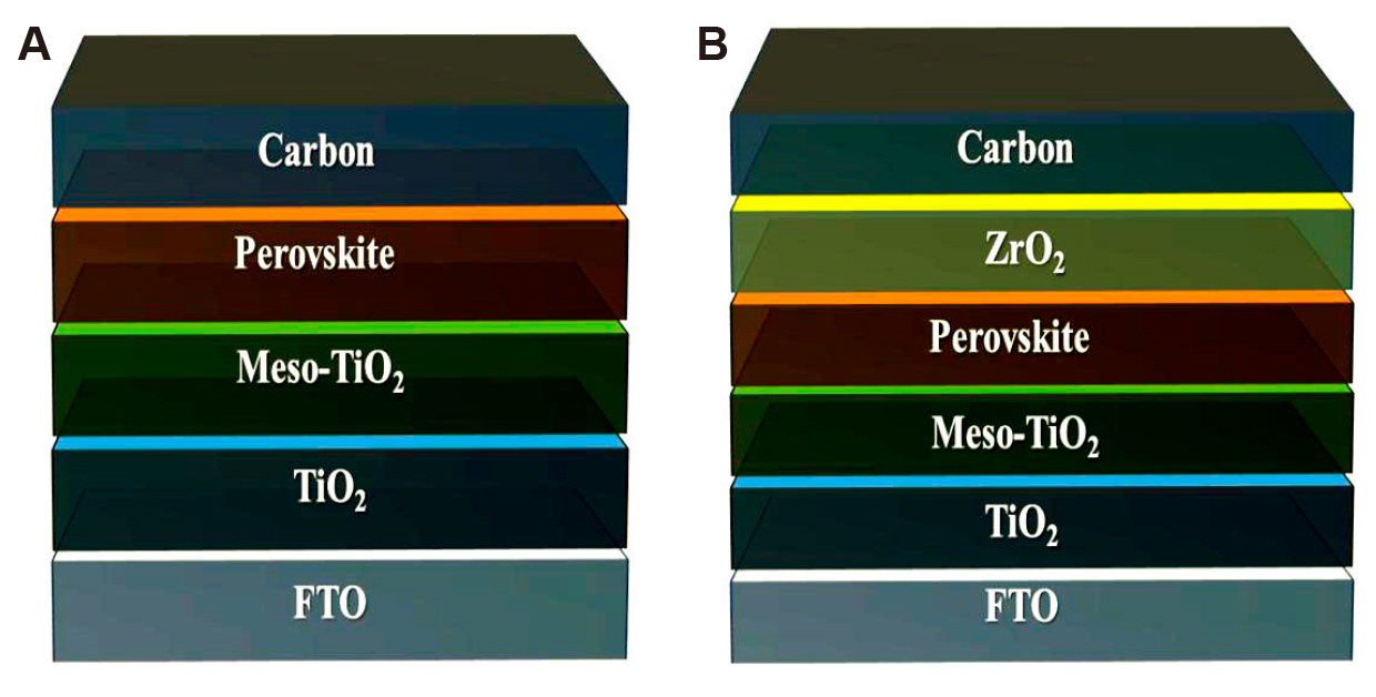
Figure 1. Device Structures of C-PSCs: (A) Bi-interfacial Structure, and (B) Tri-interfacial Structure.
For HTL-free C-PSCs to achieve optimal performance, establishing effective contact at the perovskite/CPE interface is crucial, as most carrier recombination occurs at these interfaces. Interfacial engineering techniques for the two primary C-PSCs structures are compared to highlight their respective advantages. In the bi-interfacial structure, the perovskite/CPE interface is characterized by a sequential layering of materials. Various methods can be employed to optimize perovskites, including solvent engineering, colloidal engineering, inorganic interlayer inclusion, crystallization control, and grain-orientation engineering. For modifying CPEs, strategies include adjusting the carbon paste solvent, applying pressure, improving contact points, hot pressing, binder solidification, modifying solvent dripping, and designing composite carbon layers. These techniques aim to enhance the contact quality and reduce charge recombination, ultimately boosting the efficiency of HTL-free C-PSCs. In the tri-interfacial structure, the contact conditions involve infiltration at the interfaces between the insulating layer, perovskite, and CPE. Therefore, various methods are employed to optimize the perovskite, CPE, and insulating layer. For the perovskite, modification techniques include template engineering, solvent engineering, additive engineering, post-treatment methods, the addition of excess PbX₂ (X=Br, Cl, etc.), inclusion of inorganic interlayers, and solvent vapor-assisted processing. For CPEs, effective modification strategies involve manipulating the pore structure and thickness of the carbon layer, developing a layered carbon structure, controlling the surface properties of the carbon layer, and utilizing novel materials to enhance conductivity and stability[45]. These approaches are aimed at improving the interface contact, reducing recombination losses, and ultimately enhancing the efficiency of tri-interfacial C-PSCs.
Interfacial charge accumulation and recombination in PSCs are primarily caused by interfacial defects, improper energy level alignment, and interfacial reactions and/or ion migration. These factors contribute to the well-known J-V hysteresis observed in PSCs[46]. Achieving optimal ohmic contacts at the interfaces is crucial for reducing energy barriers for charge transport. This section outlines the key functions of interface engineering in C-PSCs.
2.1 ETL/Perovskite Interface (e.g., CsBX₃)
Enhancing electron transport between SnO₂ and CsBX₃ in C-PSCs has been a focal point of research. Various materials, including organic salts, inorganic salts, metal oxides, and quantum dots (QDs), have been explored to optimize this interface[46-51]. For instance, Deng et al.[46] modified the SnO₂/CsPbI₂Br interface using KOH and NaOH. The KOH-modified C-PSC exhibited a PCE of 11.78% and showed reduced J-V hysteresis. In another study, Zhong et al.[47] introduced tetrabutylammonium acetate as a buffer layer between SnO₂ and CsPbI₃, which enhanced the electrical conductivity of SnO₂ and formed a TBAPbI₃ layer. This modification improved the PCE to 12.79%[47]. Thermal expansion, resulting in compressive and tensile strain, can also hinder electron transport at the ETL/CsPbBr₃ interface. To address this, Zhou et al.[48] incorporated WS₂ nanoflakes into the SnO₂-TiOxCl4-2x/CsPbBr₃ interface. These WS₂ nanoflakes acted as a growth template for the van der Waals epitaxy of CsPbBr₃, reducing defect density and increasing activation energies for ion migration. As a result, the PCE of the C-PSCs improved to 10.65%[52]. These examples highlight the importance of interfacial engineering in optimizing charge transport and reducing recombination in C-PSCs.
2.2 Perovskite/Carbon Interface (e.g., CsBX₃)
Traditional CsBX₃ films often suffer from inadequate surface coverage, leading to alternative charge pathways between the perovskite and CEs. Lewis basic molecules can address these surface imperfections by forming coordinate bonds with CsBX₃[53-57]. For instance, insulating polymers such as polyethyleneimine (PEI), poly(methyl methacrylate), and polyvinyl acetate have been used to enhance the perovskite-carbon interface[57-59]. Proper film thickness is essential, as deviations can negatively affect device performance. Han et al.[60] recently developed a novel 2D Cs₂PtI₆ material to protect the surface of CsPbI₂Br, achieving a PCE of 13.69%. Incorporating a heterojunction on the perovskite surface can both improve device stability and extend the light absorption range[61]. For example, combining bulk-heterojunction SnS:ZnS and J61-ITIC with CsPbBr₃ extended light absorption from 550 to 700nm and 780nm, respectively[62,63]. There is also growing interest in integrating CsPbBr₃ with poly(3-hexylthiophene) and phenyl-C₆₁-butyric acid methyl ester in BHJ C-PSCs. Yang et al.[62] used carbon black nanoparticles to create a carbon black-CsPbI2Br BHJ structure (Figure 2A), while Tong et al. applied a deposition process to add CsPb₂Br₅ and Cs₄PbBr₆ onto CsPbBr₃, forming a graded heterojunction architecture[64]. This gradient energy level reduces interaction between CsPbBr₃ and carbon and establishes an optimal charge transport pathway (Figure 2B-D).
|

Figure 2. Device Characteristics and Carrier Transport Mechanisms in Reference and Modified C-PSCs. A: J-V curves of the devices (inset: device structure and energy level alignment). Reproduced from Ref.[65] with permission from American Chemical Society. B: Schematic illustration of carrier transport mechanism in reference C-PSCs. C: Schematic of carrier transport in modified C-PSCs. Reproduced from Ref.[64] with permission from Wiley-VCH. D: Energy level diagram of C-PSCs. Reproduced from Ref.[64] with permission from Wiley-VCH.
Yin et al.[66] employed 1-butyl-3-methylimidazole hexafluorophosphate for dual interface modification in CsPbI₂Br C-IPSCs. They utilized graphene QDs, CsPbI₂Br perovskite QDs, SnO₂ QDs, and CsMBr₃ QDs (where M represents Sn, Bi, Cu) to modify the dual interfaces in C-PSCs with an FTO/CsPbBr₃/C architecture[67,68].
2.3 Anode/ETL or Perovskite Interface (e.g., CsBX₃)
Prior research often overlooked the impact of anode materials on interface properties and device PCE. Fu et al.[69] improved the FTO/ZnO interface by pretreating it with deionized (DI) H₂O to enhance wettability. The addition of PEI reduced the work function (WF) of FTO, leading to a dipole-adjusted interface between FTO and CsPbIBr₂, resulting in a PCE of 4.86%. Additionally, Ta-doped SnO₂ films have been used as bottom electrodes in C-PSCs to minimize energy level mismatches with TiO₂, achieving a PCE of 6.48%[70,71]. To enhance the efficiency of C-PSCs, several approaches have been explored: (a) Post-Treatments: Post-treatment methods have been shown to improve the efficiency of C-PSCs by enhancing perovskite film quality and device stability. (b) Deposition Techniques: Various perovskite deposition techniques, such as drop casting and inkjet printing, have been investigated to increase the PCE of C-PSCs[72]. (c) Antisolvent Treatment: Antisolvent treatments have been used to enhance the quality of the perovskite film, leading to improved PCE in C-PSCs[73]. (d) Incorporation of carbon nanodots (CNDs): Introducing CNDs into the photoactive layer of CsPbI₂Br has been found to reduce trap states and improve the crystalline structure, thus enhancing both PCE and stability of C-PSCs[74]. (e) Mixed Perovskites: Mixed perovskites exhibit better performance compared to pure perovskites, offering improved light absorption and higher PCE[75]. (f) Carbon-Based Nanomaterials: The integration of carbon-based nanomaterials has been found to enhance the performance and stability of PSCs[76]. (g) Lewis Bases: Compounds containing the cyano group used as passivation agents can improve the stability and storage of PSCs under normal conditions[77].
Emerging carbon-based materials such as graphene, GO, CQDs, graphitic carbon nitride (G-C3N4), covalent organic frameworks (COFs), and hydrogen-bonded organic frameworks (HOFs) are increasingly being utilized in PSCs due to their distinctive properties. These materials hold great potential for enhancing the overall performance of solar cells by improving electrical transport, stability, and light absorption. Regarding graphene and GO, they are known for their high electrical conductivity and flexibility, making them suitable for improving charge transport in PSCs. Additionally, graphene enhances the stability of the device by acting as a barrier against moisture and oxygen. It has been found that hydrophobic p-type GO exhibits similar effects to those of imidazole; the use of high-conductivity GO-doped PEDOT:PSS reduced contact resistance, resulting in an improvement in PCE from 15% to 18%[78]. The tunable surface properties of graphene also contribute to better interaction between the perovskite layer and the electrode. According to Li et al.[79], these characteristics have made graphene a promising component in solar cell design. As for CQDs, these are nanomaterials that provide tunable optical properties, which enhance light absorption in solar cells. CQDs help improve charge separation and reduce recombination losses, leading to higher PCE. The surface functionalities of CQDs also allow them to act as passivating agents, improving the device's stability, as indicated in a study by Zhang et al[80]. G-C3N4 is considered a promising material due to its excellent thermal and chemical stability, as well as its good photocatalytic properties. It has been used to enhance the operational stability of solar cells and improve electron transport, contributing to better charge collection, according to research by Xu et al.[81] COFs are crystalline, porous materials designed to perform specific functions in solar cells, such as enhancing charge transport and reducing hysteresis. The large surface area and adjustable porosity of COFs allow for efficient ion diffusion, making them useful for improving ion transport in solar cells. Additionally, COFs contribute to the mechanical stability of the device, as highlighted by Wang et al[82]. Finally, HOFs are porous materials that improve the structural and electronic properties of solar cells. HOFs act as structural support for the perovskite layer, enhancing stability and providing a more homogeneous distribution of the active material. The intrinsic flexibility of HOFs also allows for their use in flexible solar cells, making them suitable for portable and flexible devices, as discussed in a study by Sun et al[83]. Based on these properties, these carbon-based materials have the potential to enhance the overall performance of PSCs by improving electrical transport, increasing stability, and enhancing light absorption, making them highly promising for future applications.
To enhance the performance and efficiency of C-PSCs, optimizing the internal structural engineering of manufacturing equipment is crucial. Here’s a detailed approach: Precision in Layer Deposition involves ensuring uniform coating techniques and controlling layer morphology. Implementing advanced deposition methods such as slot-die coating, spray coating, or inkjet printing is essential to achieve uniform thickness and coverage of the perovskite layer, which minimizes defects and improves cell performance[84]. Additionally, optimizing the parameters of deposition processes such as temperature, pressure, and solvent evaporation rates can significantly enhance the morphology and quality of the perovskite layer, leading to better film quality and performance[85]. Enhanced Charge Transport is vital for improving the efficiency of C-PSCs. Utilizing advanced carbon-based materials, such as graphene and CNTs, can improve the electrical conductivity and charge transport properties of the electrodes. This reduces resistance and enhances overall efficiency[86]. Improving interface engineering is also important. Developing interfacial layers that facilitate efficient charge transfer between the perovskite layer and the electrodes can help reduce charge recombination losses and increase efficiency[87]. Thermal Management is crucial to manage the thermal load during the deposition and operation of C-PSCs. Designing equipment with effective heat dissipation mechanisms and incorporating thermal management materials helps maintain optimal processing temperatures and prevent overheating[88]. Additionally, integrating precise heating and cooling controls ensures stable processing conditions, which is critical for maintaining consistent film quality and performance across large-scale production[89]. Scalability and Adaptability in equipment design allow for flexible and large-scale production. Developing modular and adaptable equipment enables scaling up or modifying processes based on production needs, accommodating different substrate sizes and perovskite formulations[90]. Implementing automated quality control systems is also essential. These systems monitor and ensure the uniformity and quality of the deposited layers through real-time imaging and analysis tools, which detect defects and inconsistencies[91]. Material Handling and Processing play a significant role in maintaining consistent quality. Designing efficient material delivery systems ensures the consistent supply and quality of perovskite precursors and chemicals, including precise dosing and mixing to maintain solution quality[92]. Preventing contamination is also crucial. Implementing cleanroom conditions and contamination control measures helps avoid impurities that could affect the perovskite layer and other components, thereby maintaining high performance and reliability[93]. By focusing on these aspects, the internal structural engineering of equipment can be effectively optimized to improve the performance and efficiency of C-PSCs, supporting advancements in their production and deployment.
The relationship between the structure of C-PSCs and their performance is a key factor in optimizing their efficiency and stability. The interactions between the various layers of materials within the cell largely determine its overall effectiveness in converting light into electrical energy. Below, we explore some of the critical structure-performance relationships in these cells. Firstly, the composition and morphology of the perovskite layer play a vital role in determining the efficiency and stability of PSCs. The composition of the perovskite material, including the choice of cations and halides, significantly affects the bandgap, stability, and thus the efficiency of the solar cell. For instance, using mixed halide perovskites can improve performance by fine-tuning the bandgap to better suit light absorption[94]. In addition, the morphology of this layer impacts the crystallinity and grain size, which are crucial for charge carrier mobility. Larger grains with fewer grain boundaries reduce non-radiative recombination and enhance charge transport[95]. Secondly, the properties of the CE are directly linked to the overall performance of the solar cell. The materials used to construct this electrode, such as graphene or CNTs, affect the ability of the cell to collect electrical charges. High electrical conductivity in these carbon materials is essential for improving the cellʼs PCE by minimizing internal resistance[96]. Furthermore, the WF of the CE influences energy level alignment between the electrode and the perovskite layer, thereby enhancing charge extraction efficiency[97]. Thirdly, interface engineering within the cell is crucial for optimizing charge transport and reducing energy losses. The interaction between the perovskite layer, CE, and other transport layers plays a significant role in improving the performance of PSCs. Effective interface passivation can help reduce surface recombination, improving both the efficiency and stability of the cell. For example, using materials like phosphonic acid to passivate the interfaces can prevent defect formation and enhance the overall performance[98]. Fourthly, the architecture of the solar cell as a whole greatly influences its efficiency in light absorption and charge collection. Balancing the thickness of the perovskite layer and CE is essential for optimizing both light absorption and charge transport. Additionally, the stacking order of different layers, such as the perovskite, CE, and transport layers, has a substantial effect on the overall efficiency of the device. Careful optimization of the cell architecture ensures better light capture and more efficient charge collection[99].
2.4 Surface Passivation
Surface passivation is crucial for improving the photovoltaic efficiency and stability of C-PSCs. The following methods are particularly notable: (a) Surface Defect Passivation: Organic polymers such as poly (bisphenol A anhydride-co-1,3-phenylenediamine) can passivate surface defects in perovskite materials. This technique bends the energy bands at the surface, prevents Pb formation, and allows control of the Fermi level, resulting in enhanced photovoltaic performance and stability[100,101]. (b) Reduction in Trap Density and Nonradiative Recombination: Naphthylmethylamine used for passivation significantly reduces trap states and enhances resistance to nonradiative recombination, thereby improving the performance and stability of photovoltaic cells[102]. (c) Improved Efficiency and Stability: The use of 2D perovskites, such as DEAI, for interfacial passivation reduces traps, inhibits nonradiative recombination, and optimizes surface potential, leading to better efficiency and stability in PSCs[103]. (d) Enhanced Moisture Stability: Passivation with 2-amino-5-(trifluoromethyl) pyridine decreases defect presence, improves carrier mobility, and minimizes nonradiative recombination, resulting in improved efficiency and long-term stability of PSCs[104]. In summary, surface passivation enhances C-PSCs performance by reducing surface defects, trap density, and nonradiative recombination, while improving moisture stability. These findings underscore the importance of surface passivation in boosting the efficiency and stability of C-PSCs. While the literature provides various approaches to enhance C-PSCs performance, further research is needed to refine these methods for widespread commercial use and long-term stability. Although none of the abstracts address all aspects of performance improvement, the information available offers valuable insights into techniques and materials that show promise for boosting the effectiveness and durability of C-PSCs.
3 ENVIRONMENTAL RISKS AND TECHNIQUES TO IMPROVE THE DURABILITY OF C-PSCs
Diverse environmental factors can significantly affect the performance of C-PSCs during production, storage, and operation. The main issue contributing to C-PSCs instability is the degradation of perovskite materials and charge-transport components. This deterioration is often linked to factors such as humidity, oxygen, illumination, temperature fluctuations, and their cumulative effects in ambient conditions. Each factor is summarized as follows.
3.1 Moisture Infiltration
Moisture can infiltrate the perovskite, leading to the formation of perovskite hydrate. Water molecules interact with organic cations to form strong hydrogen bonds, destabilizing the chemical bonds between the cations and PbX₆ (where X = I, Br, or Cl). This interaction causes rapid deprotonation of the organic cation and subsequent breakdown of the perovskite material. The degradation is exacerbated by external stresses, such as thermal or electric fields[105-107]. Additionally, hygroscopic additives in hole transport materials (HTMs) can further degrade perovskite due to moisture[108-110].
3.2 Oxygen Exposure
Oxygen can cause oxidation in metal oxide charge transport materials, such as TiO₂, and perovskite photoabsorbers, leading to decreased PSC performance. TiO₂, in particular, undergoes oxidation when exposed to atmospheric oxygen, especially under UV radiation, forming superoxide anions. These superoxide ions contribute to the oxidative degradation of perovskite[111,112]. Oxygen can also form peroxides or superoxide species that interact with organic cations like MA⁺, accelerating the dissolution of the perovskite material[111]. For instance, the reaction between light and oxygen can decompose MAPbI₃ perovskite into PbI₂, I₂, H₂O, and gaseous CH₃NH₂[113,114].
3.3 Light Exposure
The breakdown of MAPbI₃ can occur due to the combined effects of light and oxygen, but also in the absence of oxygen. High-energy photons, exceeding 3 electron volts, can excite electrons in the valence band, leading them to fill anti-bonding orbitals of NH₃. This excitation breaks the NH bonds in MA⁺, generating gaseous CH₃NH₂ and H₂. Additional carriers and photogenerated electrons trapped in the conduction band can further accelerate these chemical processes in the presence of oxygen. Furthermore, light-induced separation of cations and halides contributes to the reduced stability of perovskite materials[115].
3.4 Thermal Stress
The degradation of C-PSCs due to heat arises from several factors. Firstly, perovskite materials generally have limited thermal conductivity, which hampers effective heat dissipation. Excessive heat accumulation induces significant thermal stress, leading to the degradation of photovoltaic systems[116,117]. This issue is exacerbated by the use of thick carbon layers (≥10µm) as back electrodes[118]. Additionally, interactions between MA⁺ cations in perovskite and carbon atoms in the carbon layers can further degrade perovskite photoabsorbers[119]. Organic HTMs, such as spiro-OMeTAD, are also prone to thermal instability and degradation at elevated temperatures, which can negatively affect device performance[120]. To enhance the long-term durability of C-PSCs, efforts can be categorized into two primary approaches: (1) improving inherent stability and (2) strengthening encapsulation. Enhancing the intrinsic stability involves optimizing the materials and device architecture to resist environmental stressors, while effective encapsulation techniques protect the device from moisture, oxygen, light, and thermal stress, thereby prolonging its operational life[109,121,122].
CEs are widely used in various energy devices, including PSCs, due to their high conductivity, chemical stability, and low cost. They serve as an essential component in the electrode layer, facilitating charge transport and collection[123]. CEs are primarily composed of different forms of carbon materials. Graphite, a highly ordered carbon structure, offers excellent conductivity and is commonly used in these applications[124]. Carbon black, an amorphous form of carbon with a high surface area, is frequently employed to enhance the conductivity of the electrode[125]. CNTs are nanostructured materials that exhibit exceptional electrical conductivity and mechanical strength, making them an attractive choice for advanced CEs[126]. Additionally, graphene, a single layer of carbon atoms arranged in a hexagonal lattice, provides both high conductivity and flexibility, making it suitable for improving the efficiency of charge transport[125]. C₆₀, spherical carbon structures, are also used in certain high-performance applications where unique electronic properties are needed[127]. Based on their structure and processing methods, CEs can be classified into several categories. Powder-based CEs are produced by dispersing carbon powders, such as graphite and carbon black, into a binder to form a paste that is then deposited onto a substrate[124]. CNT electrodes are constructed from CNTs that are either deposited as a thin film or woven into a network to enhance conductivity[126]. Graphene-based electrodes utilize graphene sheets to increase flexibility and surface area, thereby enabling more efficient charge transport[125]. Finally, composite CEs combine various carbon materials, such as graphite and carbon black, with other additives to optimize conductivity and mechanical properties[127]. C-PSCs can be classified into two categories listed below.
3.5 CEs for Monolithic-Structured C-PSCs
For the production of CEs in monolithic-structured C-PSCs, materials must be compatible with carbon paste, which is essential for their fabrication. CEs can be composed of one, two, or more carbon materials. Initially, CEs can be fabricated using a single carbon material known for its easy graphitization, high electrical conductivity, and a structure that supports the infiltration of perovskite precursors[33,128]. For example, aloe vera CEs developed by Mali et al.[33] achieved a PCE of 12.58%. Despite the absence of encapsulation, this device maintained 80% of its initial PCE after being exposed to an environment with relative humidity (RH) exceeding 65% for 1,000h (Figure 3A). Similarly, needle coke electrodes created by Zhong et al.[128] yielded a PCE of 11.66%. The device, lacking protective covering, retained 90% of its initial PCE after 40 days in the air[33,128]. Liu et al.[129] utilized a 1.8μm thin film of single-walled CNTs as the back contact in a monolithic structure, achieving a PCE of 12.7% and stability for 300h under dark conditions. Additionally, Luo et al.[130] fabricated a device incorporating a substrate with NiOx, Al2O3, and SnO2@CNTs, which achieved a PCE of 14.3% and maintained over 88% of its initial PCE after 550h under full light and nitrogen. Secondly, in addition to single-carbon material electrodes, CEs can also be manufactured using graphite and carbon black. The morphology and electrical conductivity of these materials influence the penetration of perovskite precursors and the efficiency of charge transfer[131,132]. The stability of C-PSCs using a binary combination of graphite and carbon black has been extensively studied[133-142]. Laboratory-scale cells employing this combination have achieved a PCE of 17%[133]. These cells, without encapsulation, demonstrate high stability in ambient air, maintaining performance for over 4,500h[134]. They also exhibit photostability of approximately 1,000h under 100mW·cm−2 illumination[135]. When encapsulated, these devices maintain thermal stability at 85℃ in the absence of light[133]. Large-scale perovskite solar modules (PSMs) using this combination have achieved a 10% PCE (Figure 3B). Encapsulated modules have shown long-term stability for over a year in darkness[136], photostability for 10,000h under 1 sun illumination at 55℃[137], and operational stability for 1,000h under continuous AM1.5 illumination at maximum power point (MPP) in ambient air[136]. Overall, binary mixture electrode C-PSCs exhibit remarkable long-term stability. Third, the integration of graphite, carbon black, and functional additives significantly improves the alignment of energy levels and the conductivity of back contacts in electrodes with varied components. Zhou et al.[138] demonstrated that incorporating WO3 nanoparticles as dopants into a mixture of graphite and carbon black increased the PCE from 7% to 10.8%. These doped materials also showed exceptional long-term stability, maintaining their performance for over 150d in air, as shown in Figure 3C[138]. Bhandari et al.[139] further validated that WO3 nanoparticles enhance the stability of devices, extending their photostability from 350 to over 500h without encapsulation. Additionally, Li et al.[140] employed a thin layer of multi-walled CNTs (MWCNTs) sprayed onto graphite and carbon black composites to improve electrode conductivity and charge transfer. Their device, which was unencapsulated, retained over 80% of its original PCE after 500h of exposure to ambient air (Figure 3D)[140].
|
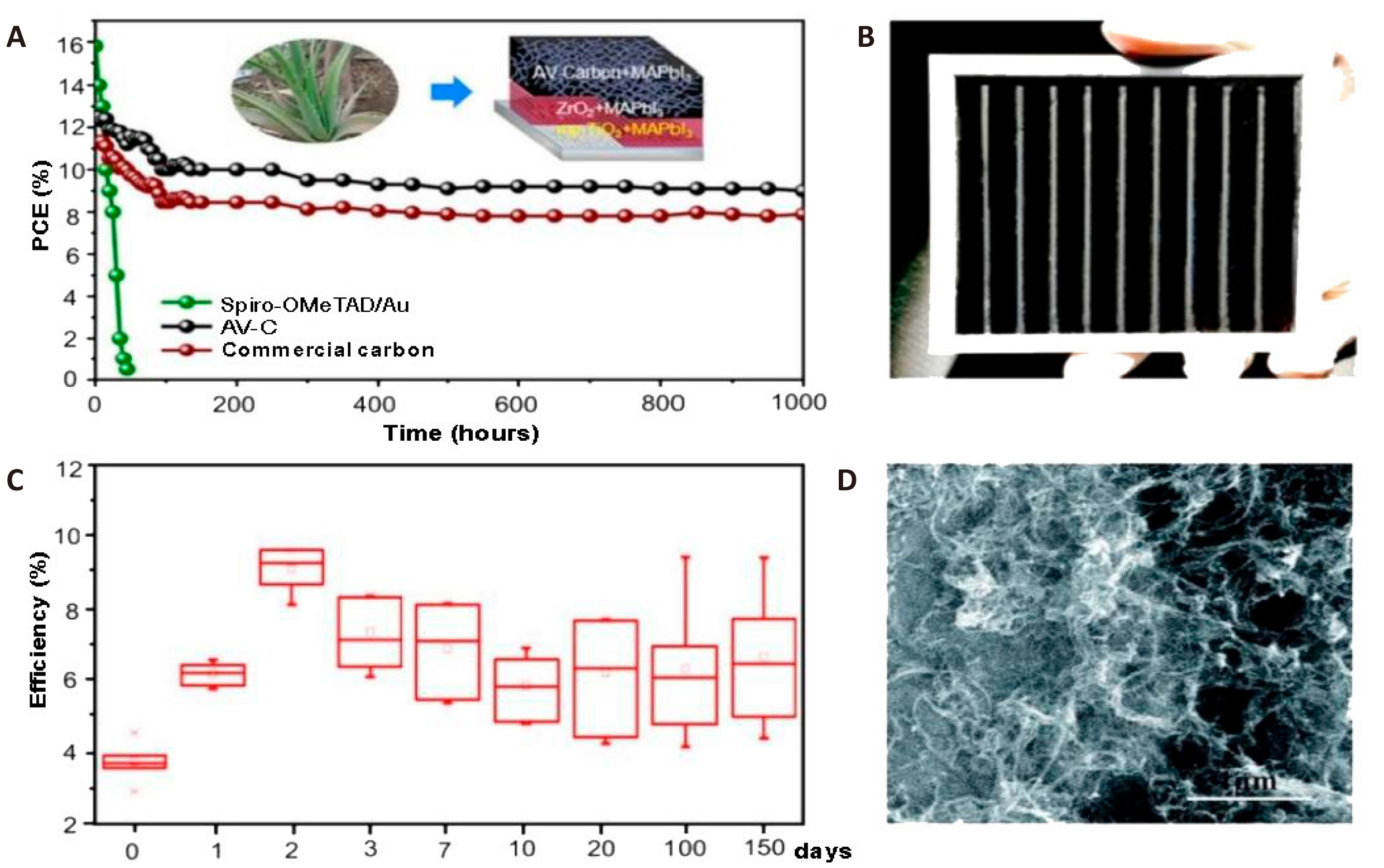
Figure 3. Long-term Stability of Carbon-Based Perovskite Solar Cells with Different Electrode Configurations. A: Long-term stability of PSCs based on AV-C, commercial carbon paste, and spiro-OMeTAD/Au at 65% RH; schematic of C-PSCs based on AV-C electrodes. Reproduced from Ref.[33] with permission from American Chemical Society. B: 10×10cm2 carbon-based PSM image with graphite carbon black composite CE[136]. Reproduced from Ref.[136] with permission from Wiley-VCH. C: Long-term stability of 10 PSCs employing CEs with WO3 additive in ambient air. Reproduced from Ref.[138] with permission from Springer Nature. D: Scientific MWCNT layer top-view SEM image. Reproduced from Ref.[140] with permission from Royal Society of Chemistry.
3.6 CEs for Layer-by-layer Structured C-PSCs.
In layer-by-layer configurations, the perovskite or HTM film is typically prepared prior to the deposition of CEs. The carbon paste or a separate carbon layer is then applied and precisely cut using a laser or transferred through pressure. Wei et al.[36] developed an affordable biocarbon electrode utilizing candle soot, which achieved a PCE of 11.02%. The device, which was not encapsulated, retained 85% of its initial PCE after 30 days of exposure to ambient air[36]. Similarly, Meng et al.[34] created low-cost, eco-friendly electrodes from materials such as coal, corn stalk, peanut shell, and bamboo chopsticks. Among these, the device using bamboo chopsticks exhibited notable efficiency and stability. As shown in Figure 4A, this device retained 87% of its initial PCE after 2,000h in ambient air without encapsulation[34,141]. Amorphous carbon, while cost-effective and environmentally friendly, has limited graphitization, leading to reduced conductivity in biocarbon products. In contrast, graphite and carbon black are commonly used to produce CEs due to their affordability, high conductivity, and the ease of application through techniques such as doctor or screen printing[26,142]. In 2014, Zhou et al.[30] introduced low-temperature CEs for PSCs using conductive carbon paste. Their contact angle tests indicated significant hydrophobicity, and the device showed environmental stability for up to 2,000h[30]. Chu et al.[147] developed a composite paste of graphite and carbon black compatible with low-temperature PSCs. This composite achieved a PCE of 13.5% and could be applied as a paintable coating. The unencapsulated device retained over 90% of its initial PCE after 960h in an environment at room temperature and 50% RH.
To address the potential misalignment of energy levels and charge transport in graphite-carbon black composites, Ding et al.[143] incorporated Pt: Ni alloy nanowires into the carbon paste. This enhancement led to a PCE of 7.86%, with the device maintaining stability after exposure to air with 80% RH for 20d[143]. Zhang et al.[144] employed a unique method involving vibrations to compact the carbon layer, achieving a notable PCE of 11.49% and excellent stability. Wang et al.[145] enhanced the efficiency of charge transfer by incorporating CNTs into both the perovskite precursor and carbon paste. This modification resulted in a device with a PCE of 15.73%[145]. Devices without encapsulation showed no degradation even under high humidity (65±5% RH) and temperature (75±5℃) conditions after being stored in darkness for 90 days. Kim et al.[146] employed C4F8 vacuum fluorine plasma for post-treatment of CEs, resulting in a device with a PCE of 14.86%. This posttreatment method differs from the pretreatment methods used on CEs. Figure 4B demonstrates that the device maintained 95% of its initial PCE after being exposed to air for 1,000h. This preservation can be attributed to the combined effect of hydrophobic fluorine atoms and CEs (Charge Extraction Layers). Liu et al.[147] developed a straightforward CE posttreatment method using acetate salt. Devices that were not enclosed maintained their initial PCE for a minimum of 4 months when exposed to the air. While excessive moisture can cause the decomposition of perovskite crystals, maintaining a controlled level of ambient humidity can potentially improve the lifespan of C-PSCs. Yan et al.[148] achieved a PCE of 14.77% by performing moisture-assisted post-annealing for a duration of 2h at RH of 30%. The exposed device did not deteriorate after 150d in a dark environment.
Carbon cloths and carbon fibers, known for their use as catalysts or counter electrodes in dye-sensitized solar cells, lithium batteries, and supercapacitors, have also been explored in PSCs. Gholipour et al.[149] utilized a cost-efficient carbon cloth electrode as a composite hole collector and degradation inhibitor for PSCs, achieving a PCE of 15.29%. However, while carbon materials serve effectively as a back contact, they can impede the migration of noble metal ions to the perovskite layer. Additionally, interactions between spiro-OMeTAD+ and migrating iodide ions may contribute to gradual degradation of the device. The deviceʼs initial PCE declined by approximately 50% after 115h of MPP tracking under continuous illumination of 100mW·cm⁻² at 85℃ in a nitrogen (N₂) environment. CNTs exhibit p-type semiconducting behavior, with a natural WF between 4.7 and 5.1eV under standard temperature and pressure conditions. In recent years, CNTs have emerged as promising candidates for use as HTMs and back electrodes in C-PSCs. For example, Wei et al.[150] demonstrated the use of MWCNTs as back electrodes in PSCs, achieving a PCE of 12.67%. Remarkably, these cells retained 90% of their initial PCE after 10 days in the dark[150]. Similarly, Luo et al.[151] reported a PCE of 10.54% in PSCs by utilizing cross-stacked, super-aligned CNT sheets doped with iodine. These devices, when exposed to dark ambient conditions for 1,500h, maintained over 93% of their original PCE. Additionally, after 400h of constant air illumination, more than 87% of their initial efficiency was preserved. In another study, Zheng et al.[32] achieved a PCE of 15.23% using boron-doped MWCNT back contacts. Their unencapsulated devices demonstrated PCE retention of 98% after 80 days in dry air, 85% after 14d at 80℃, and 93% after 14 days in a high-humidity environment (60% RH). However, the shallow WF and lack of reflectivity in CNTs have posed challenges for further improving the performance of CNT-based PSCs, despite their favorable properties. Lee et al.[152] tackled this issue through vapor-assisted ex situ CNT doping, which significantly enhanced the efficiency and stability of PSCs (Figure 4C). Their CNT-based device, doped with trifluoromethanesulfonic acid (TFMS), achieved a PCE of 17.6%. Moreover, it retained 86.9% of its initial PCE after being subjected to a nitrogen atmosphere at 60±5℃ and 50±10% RH for 244h. This result is illustrated in the accompanying Figure 4D. Additionally, as shown in Figure 4E, TFMS doping led to a notable increase in the hydrophobicity of the CNT film, further contributing to the deviceʼs stability. Luo et al.[153] utilized CNTs as back electrodes in flexible PSCs, and the devices demonstrated impressive stability, retaining 92% of their initial PCE after 1,014h of continuous illumination, and 89% after being heated at 60℃ for 1,570h in a dark environment. These results highlight the potential of carbon-based electrodes in improving stability. Additionally, p-i-n planar PSCs are becoming more popular due to their simple fabrication and minimal hysteresis. However, long-term stability is often compromised by ion migration between noble metal electrodes and the perovskite layer. Zhou et al.[154] tackled this issue by employing PEI-modified carbon CNT films as back contacts in an inverted device configuration. Remarkably, the device without encapsulation maintained over 94% of its initial PCE after 500h of air exposure. Furthermore, an encapsulated version of the device, after being stored for 500h at 60℃ and 60% RH, retained 85% of its original PCE. Carbon films can be employed independently to create durable PSCs that exhibit long-term stability without any detrimental effects from the solvents in the carbon paste on the perovskite or HTM layers. In 2015, Wei et al.[155] developed a device with a carbon film back contact, achieving a PCE of 13.53%. After 20 days in ambient conditions, the PCE dropped slightly from 13.53% to 12.87%, demonstrating good atmospheric stability. Zhang et al.[14] later introduced a self-adhesive carbon film back electrode with a PCE of 19.2%. As depicted in Figure 4F, the unencapsulated device retained over 95% of its initial PCE after 1,000h in ambient air and 94% after 80h in N2 (Figure 4G-H). Additionally, Su et al.[156] fabricated a macroporous carbon membrane with self-adhesive properties for PSCs with a 1cm² active area, achieving a PCE of 17.02%. The device, without encapsulation, maintained 90.5% of its original PCE after 1,500h of darkness at 20℃ and 30% RH. These studies collectively underscore the potential of carbon-based electrodes in enhancing the long-term stability and durability of PSCs, making them a promising candidate for scalable and stable solar energy applications.
|
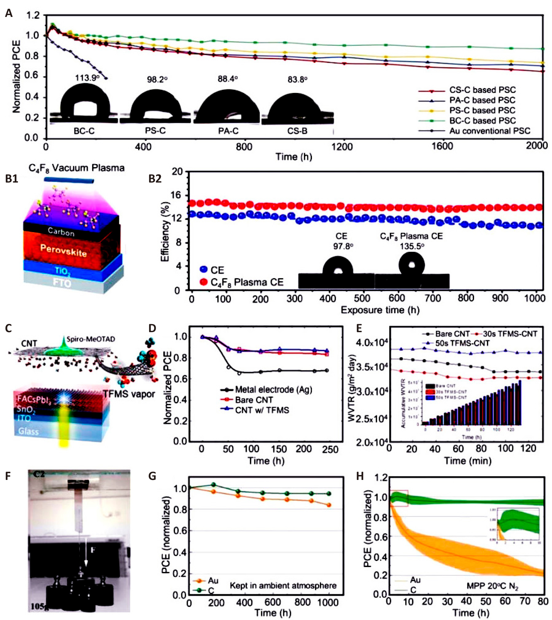
Figure 4. Stability and Performance of Biocarbon Electrode-based Perovskite Solar Cells Under Various Conditions. A: Stability testing of biocarbon electrode-based and conventional PSCs in an ambient atmosphere with 30% RH at RT; the inset shows contact angle tests on several biocarbon CEs. Reproduced from Ref.[141] with permission from Elsevier. B: The diagram shows the long-term stability of C-PSCs with and without C4F8 vacuum plasma treatment under controlled ambient conditions (25℃; 40%±5% RH). The contact angle test results are shown in the inset. Reproduced from Ref.[146] with permission from Royal Society of Chemistry. C: Schematic of TFMS-doped CNT back electrode planar heterojunction PSCs. Reproduced from Ref.[157] with permission from American Chemical Society. D: PCE evolution of encapsulated devices (60±5℃, 50%±10% RH) under constant 1 sun illumination in open circuit conditions. Reproduced from Ref.[157] with permission from American Chemical Society E: Water vapor transmittance rates of bare CNT film (black), 30s vapor-doped film (red), and 50s film (blue)[157]. Reproduced from Ref.[157] with permission from American Chemical Society. F: Gravity-based self-adhesive carbon film adhesive force test. Reproduced from Ref.[14] with permission from Wiley-VCH. G: Unencapsulated PSC stability test in ambient air. Reproduced from Ref.[14] with permission from Wiley-VCH. H: PSC aging test under continual illumination at MPP in N2 at 20℃. Reproduced from Ref.[14] with permission from Wiley -VCH.
Achieving significant breakthroughs in the performance of C-PSCs involves addressing both efficiency and challenges. Key factors contributing to enhancing these aspects include perovskite layer engineering, CE optimization, fabrication techniques, and interface engineering. For perovskite layer engineering, composition optimization is crucial. Adjusting the perovskite composition by incorporating different halides and cations can tune the bandgap and improve light absorption, thus maximizing the PCE by better matching the solar spectrum[158]. Additionally, additive engineering plays a significant role. Using additives such as polymers or small molecules can enhance the perovskite filmʼs quality, improve crystallinity, and reduce defects. These additives also passivate surface and bulk defects, leading to higher efficiency and reduced non-radiative recombination[159]. To enhance stability, advanced encapsulation techniques protect the perovskite layer from environmental factors like moisture and oxygen, which are detrimental to stability. Effective encapsulation extends the operational lifetime of PSCs[160]. Research into more stable perovskite compositions and hybrid materials can improve resistance to degradation. Mixed-halide perovskites, for example, offer enhanced stability compared to single-halide counterparts[161]. Regarding CE optimization, material upgrades are essential. Utilizing high-conductivity carbon materials such as graphene or CNTs can significantly improve charge transport and collection. Enhanced conductivity reduces resistive losses and improves overall device efficiency[162]. Interface engineering also plays a role. Modifying the interface between the CE and the perovskite layer can reduce charge recombination and improve charge extraction. Employing interfacial layers or surface treatments can optimize the charge transfer processes[96]. For stability enhancements, developing CEs with better environmental stability can prevent degradation. Incorporating protective coatings or stabilizers can extend the lifespan of carbon-based electrodes[161]. Flexible substrates also contribute to durability under mechanical stress, maintaining the structural integrity of the solar cells, particularly in applications involving bending or stretching. In fabrication techniques, scalable production methods such as roll-to-roll processing and inkjet printing enable large-scale production with high uniformity. This scalability is crucial for achieving consistent efficiency across large areas[163]. Precision deposition techniques, including vacuum-based methods and solution-processing improvements, can enhance layer quality and uniformity, contributing to higher efficiency[164]. Stability can be further improved by optimizing fabrication conditions such as temperature, humidity, and deposition rates, which helps in minimizing defects and improving film integrity[159]. Finally, interface engineering impacts both efficiency and stability. Introducing interfacial layers between different components of the solar cell can enhance charge transport and reduce recombination losses, thus optimizing the efficiency of C-PSCs[165]. Applying barrier layers that protect the perovskite layer from moisture and oxygen can significantly improve stability, preventing the ingress of harmful substances and prolonging the operational life of the cells[160].
CEs present several advantages over metal electrodes in PSCs. One notable benefit is their cost-effectiveness and material availability. CEs, including graphite, carbon black, and graphene, are significantly cheaper and more abundant than metal electrodes such as Au or Ag. This reduces the overall cost of PSCs, making them more viable for large-scale production[162]. Additionally, CEs offer superior flexibility and mechanical properties compared to metals. Materials such as graphene and CNTs provide excellent mechanical strength and flexibility, which is beneficial for creating flexible PSCs. This flexibility allows for diverse applications, including wearable electronics and flexible displays[166]. In terms of chemical stability, CEs are less prone to corrosion and degradation compared to some metals. They exhibit better performance in environments with moisture and oxygen, which enhances the stability and longevity of PSCs under operational conditions[86]. CEs also improve light absorption and scattering within PSCs. Carbon black, with its high surface area, effectively scatters light, increasing the effective path length of light within the perovskite layer. This enhances light absorption and can improve the overall efficiency of the solar cell[167]. Moreover, advanced carbon materials provide excellent charge transport properties. CNTs and graphene, known for their high electrical conductivity, enhance charge transport and collection in PSCs. This improvement reduces series resistance and boosts the overall PCE of the solar cell[162].
4 USING CES TO REDUCE THE COST OF C-PSCs
While metal-electrode-based PSCs presently have the highest PCE records, C-PSCs have made notable progress, achieving a top PCE of 22.4%, which was verified in December 2020[5,14]. As of 2023, Au-PSCs have reached PCEs greater than 26%, surpassing previous PSCs that use gold counter electrodes[168]. Au is a highly effective electrode option for PSCs in terms of performance and material qualities. However, its commercialization for PSCs is not feasible due to its high cost and limited availability. To supply the world electricity consumption of 2035, which is estimated to be 40,000TWh, around 206 thousand metric tons of Au would be needed for Au-PSCs. This amount is over ten times more than the Au reserves recorded in 2023. Thus, considering the abundance of materials, utilizing Au as an electrode material for PSCs might impede the expansion of PSCs as a widely used clean energy technology. When considering the thicker electrode coatings and lower device efficiencies, the relative resource requirements for C-PSCs are still more advantageous in comparison. Figure 5 clearly indicates that CEs are a more sustainable option than Au, considering both material production and availability. Currently, the worldwide supply of natural graphite is sufficient to fulfil 5.13% of the global power demand in 2035 using C-PSCs. However, the current global Au output can only achieve 1.5% of this goal using Au-PSCs. Significantly, the natural graphite reserves projected for 2023 are over ten times greater than the amount of graphite needed to fulfil the worldwide electricity demand by 2035 utilizing C-PSCs[169-171]. Hence, considering the abundance of carbon, its utilization as an electrode material in PSCs has the potential to make PSC upscaling a widely adopted clean energy technology.
|
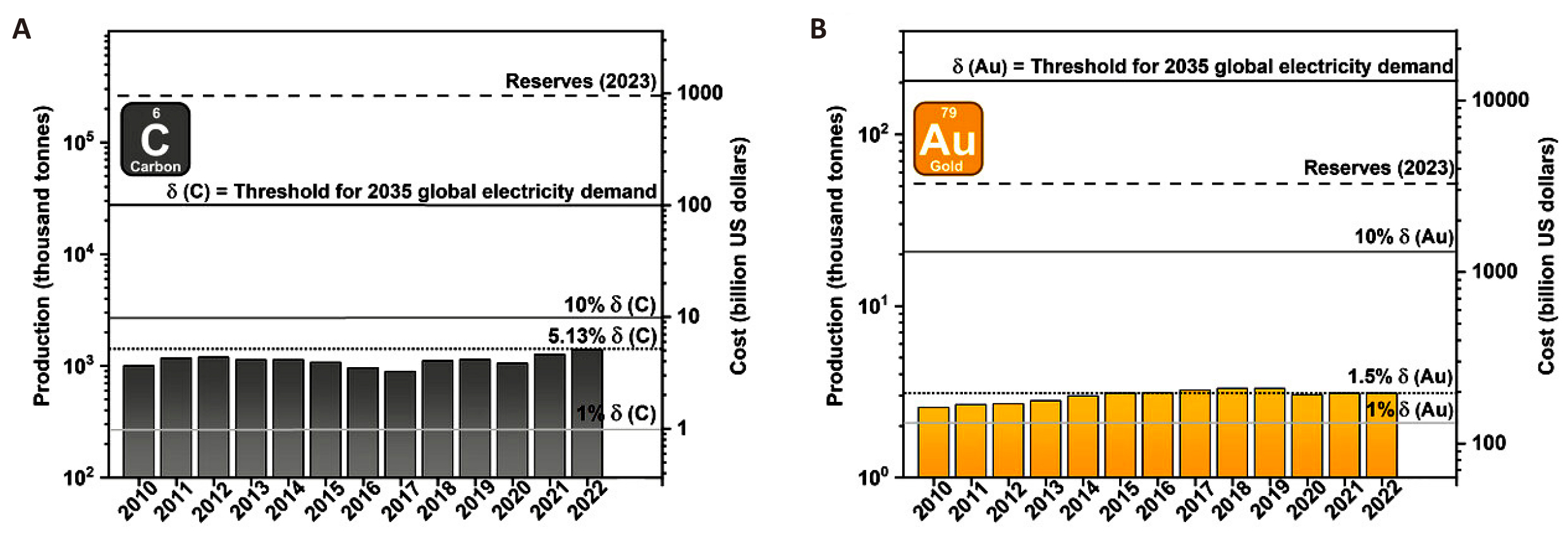
Figure 5. Trends in Global Production and Associated Costs of Natural Graphite and Gold during the Past Decade. A: the solid black line, labelled δ(C), represents the amount of graphite needed to fulfil the projected world energy demand by 2035 using C-PSCs. The grey lines indicate different proportions of δ(C). The dashed line indicates the projected worldwide graphite reserves for the year 2023. B: the quantities for gold are shown, with δ(Au) representing the mass of gold needed to fulfil the projected world energy demand for 2035 utilizing Au-PSCs. Reproduced from Ref.[172] with permission from Wiley-VCH.
The cost advantages of using carbon as the counter electrode material compared to gold further highlight its benefits. Currently, high-purity micronized graphite costs approximately USD 3,650 per metric ton, whereas gold is priced at over USD 63.9 million per metric ton, resulting in a cost differential of 18,000 times. In the context of Figure 5[172], this translates to a financial commitment of USD 10 trillion for Au electrodes versus USD 100 billion for CEs in PSCs, considering only raw material costs. A 2017 manufacturing analysis by Chang et al.[248] found that Au evaporation significantly impacts the cost of PSC production. Their research indicated that 90% of the expenses associated with manufacturing devices are due to materials, with gold alone accounting for 76% of the total cost. The advantages of using carbon in PSCs are further reinforced when considering environmental impacts. Gold mining results in approximately 12,500kg of CO2 emissions per kilogram of gold produced, whereas natural graphite powder generates an estimated 2.2 to 9.6kg of CO2 emissions per kilogram of material. Additionally, a study by Gong et al.[173] demonstrated that an Au electrode with a thickness of 100nm has the highest embodied energy compared to all other materials used in perovskite module fabrication. Au, among all module components, exerts the most significant impact on various environmental effects that are challenging to quantify, as noted in their research. However, recent life cycle assessments indicate that the CE synthesis has a minimal environmental impact on C-PSCs compared to the perovskite layer itself[174]. Furthermore, recent research highlights that CEs derived from waste materials such as printer toner and biomass materials-including cellulose, coconut husks, aloe vera, bamboo chopsticks, corn husks, and peanut shells-show promising results for C-PSCs. This suggests a potential sustainable alternative for C-PSCs by introducing additional viable feedstock options[33,141,175-177].
4.1 Manufacturing Costs of PSCs: A Comparative Analysis
The manufacturing costs of including normal PSCs (N-PSCs), inverted PSCs (I -PSCs), and HTL-free C-PSCs (1m²) were calculated and compared in detail by Li et al.[178] taking into account material costs, equipment depreciation, and energy consumption, irrespective of efficiency and stability. By replacing the metal electrode and HTL with a CE, the production costs for C-PSCs were reduced to varying extents when compared to the other two types of PSCs. Consequently, the total cost of C-PSCs decreased from $86.49 and $81.31 to $41.16, reflecting a substantial cost reduction of 49% to 52%, positioning C-PSCs as a promising candidate for next-generation, cost-effective photovoltaic technology[178].
The material costs for various PSCs were calculated and categorized into five main components: the conducting substrate, ETL, perovskite layer, HTL, and counter electrode. For each category, the most widely used and representative materials were selected for comparison. They carefully considered the selection of different active layers and potential combinations of device structures in PSCs. For instance, TiO₂, SnO₂, PCBM, and fullerene (C₆₀) were used as ETLs, while Spiro-OMeTAD, PTAA, PEDOT: PSS, and NiO were used as HTLs. Additionally, Au, Ag, and carbon paste were considered for use as counter electrodes. In our calculations, they assumed the PSCsʼ area to be one square meter, and the formula applied is as follows, which aligns with that used by Mathews et al[149].
$${P}_{2}={P}_{1}\times\frac{{log}\frac{{P}_{1}}{{P}_{R}}}{{log}\frac{{W}_{1}}{{W}_{R}}}\times\left(\frac{{W}_{2}}{{W}_{1}}\right)\left(1\right)$$
where P₂ represents the price per unit of the material purchased at the amount W₂. The known prices P₁ and PR per unit at their respective material amounts serve as reference points for calculating the price at W₂. For calculation simplicity, the same transparent conductive substrate and perovskite layer were considered. While ITO offers excellent light transmittance and electrical conductivity, indium is an expensive and rare metal, and ITO is brittle. In contrast, FTO has a relatively low raw material cost, priced at $10.40/m², and offers good chemical resistance, remaining stable in most chemical environments. Thus, FTO glass was selected as the transparent conductive substrate. For the perovskite layer, the advanced triple-cation ((FAPbI₃)₀.₈₇(MAPbBr₃)₀.₁₃)₀.₉₂(CsPbI₃)₀.₀₈ perovskite was chosen, as it is commonly used in high-efficiency PSCs[179-182]. After calculation, the total cost of the perovskite layer was approximately $0.62/g, contributing minimally to the overall material cost. For N-PSCs, TiO₂ and SnO₂ have been demonstrated to be effective ETLs, both with low and comparable material costs of about $2.64/g and $2.25/g, respectively. However, the widely used HTL, Spiro-OMeTAD, is significantly more expensive, priced at $40.08/g. Additionally, noble metals like Ag and Au are often used as counter electrodes in cutting-edge N-PSCs, costing around $0.71 and $58.77, respectively. Therefore, if TiO₂, Spiro-OMeTAD, and Ag are used, the total cost would reach $49.58; if Au is used instead of Ag, the total cost could soar to $162.26. For I-PSCs, the most efficient ETLs are C₆₀ or its derivative, PCBM, with material costs of $24.61/g and $86.75/g, respectively. Commonly used HTLs include organic materials such as PTAA and PEDOT:PSS, and the inorganic NiO. PTAA, in particular, is highly expensive at $220.54/g. Even with more cost-effective choices such as PEDOT: PSS, C₆₀, and a Ag electrode, the total material cost remains at $44.52, which is comparable to that of N-PSCs. Although NiO is considerably less expensive than other HTL materials, high-efficiency I-PSCs typically use a double HTL layer consisting of NiO and self-assembled molecules (SAMs)[183,184]. SAMs are both costly and complex, making NiO less suitable for direct comparison at this time. In contrast, C-PSCs replace both the HTL and the metal electrode with a CE, significantly lowering material costs. To ensure adequate conductivity, the carbon paste thickness is approximately 20μm, much thicker than that of a metal counter electrode. However, since carbon paste is priced at only $0.01/g equivalent to just 1.4% of the cost of Ag ($0.71/g) the material cost of CEs is substantially lower than that of Ag electrodes. As a result, the total material cost of C-PSCs amounts to about $15.04. Upon calculation, it was found that the material cost of C-PSCs decreased by approximately 69.7% and 66.2% compared to N-PSCs and I-PSCs, respectively. This cost reduction is primarily attributed to the absence of HTL in C-PSCs and the much lower cost of CEs compared to precious metal electrodes[178]. In summary, it is clear that C-PSCs offer a significant advantage in terms of material costs.
5 FABRICATION TECHNOLOGIES C-PSCs WITH LARGE WORKING AREA
The development of PSCs has witnessed significant improvements due to novel materials and innovative fabrication techniques. CEs have emerged as a crucial alternative to traditional metal electrodes because of their low cost, stability, and abundant availability. However, the high performance of these solar cells heavily depends on the interaction between the perovskite layer, the CE, and other functional materials. Novel materials have played a critical role in solving many challenges associated with C-PSCs. For instance, mixed-cation perovskites such as FA-Cs or MA-FA have shown enhanced thermal and chemical stability, which is crucial for long-term operation[185]. Additionally, passivation materials, including both organic and inorganic interfacial layers, have been introduced to improve perovskite crystallinity and reduce surface defect states. This reduces charge recombination and boosts solar cell efficiency[186]. Carbon materials themselves have also seen significant advancements. For example, CNTs and graphene-based composites offer improved conductivity and better integration with perovskite layers. These materials not only enhance charge collection but also increase the flexibility and durability of the solar cells[187]. Moreover, the use of HTMs compatible with CEs, such as polymeric HTMs or HTM-free designs, has reduced energy losses during charge extraction[188]. Fabrication techniques have also evolved to meet the specific needs of C-PSCs. For example, low-temperature processing methods have been critical for integrating CEs with the perovskite layer without damaging its structure. Techniques like slot-die coating, spray deposition, and inkjet printing allow for scalable production while maintaining high-quality film formation[186]. These methods also enable the fabrication of large-area devices, which is essential for commercial viability. Furthermore, techniques aimed at improving perovskite film quality, such as solvent engineering and additive engineering, have been used to achieve uniform and pinhole-free perovskite layers. This is particularly important in C-PSCs, where the interface between the perovskite and the CE is crucial for efficient charge transport[187].
PSMs are typically fabricated using two primary methods: solution processing and vapor deposition processes. These methods are based on the perovskite film preparation techniques and can be classified into the following subcategories (Figure 6)[189]: The solution processing techniques include spin coating, blade coating, slot-die coating, spray coating, inkjet printing, screen printing, as well as vapor deposition methods such as vacuum thermal evaporation, chemical vapor deposition, and flash evaporation.
|
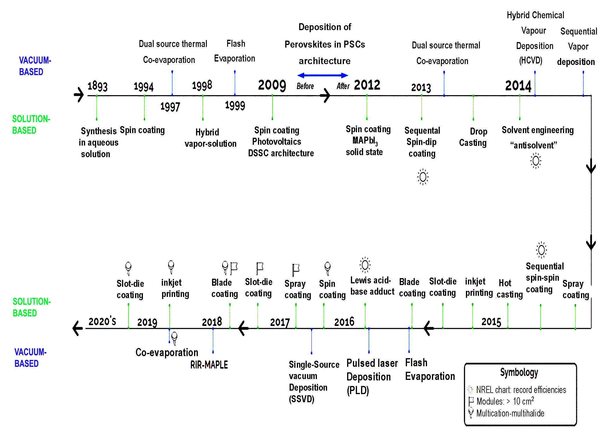
Figure 6. Timeline of the Progress in Thin-Film Manufacturing Methods for Inorganic and Hybrid Halide Perovskites. The methods are classified into vacuum-based and solution-based. The symbols in the inset depict the manufacturing methods used for modules, multi-halide compositions, and the NREL record efficiencies claimed. Reproduced from Ref.[189] with permission from AIP Publishing.
PSMs with CEs can be classified based on the methods used for fabricating the CEs (Figure 7). These methods include solution-based techniques and various printing methods, as illustrated in Figure 7[190].
|
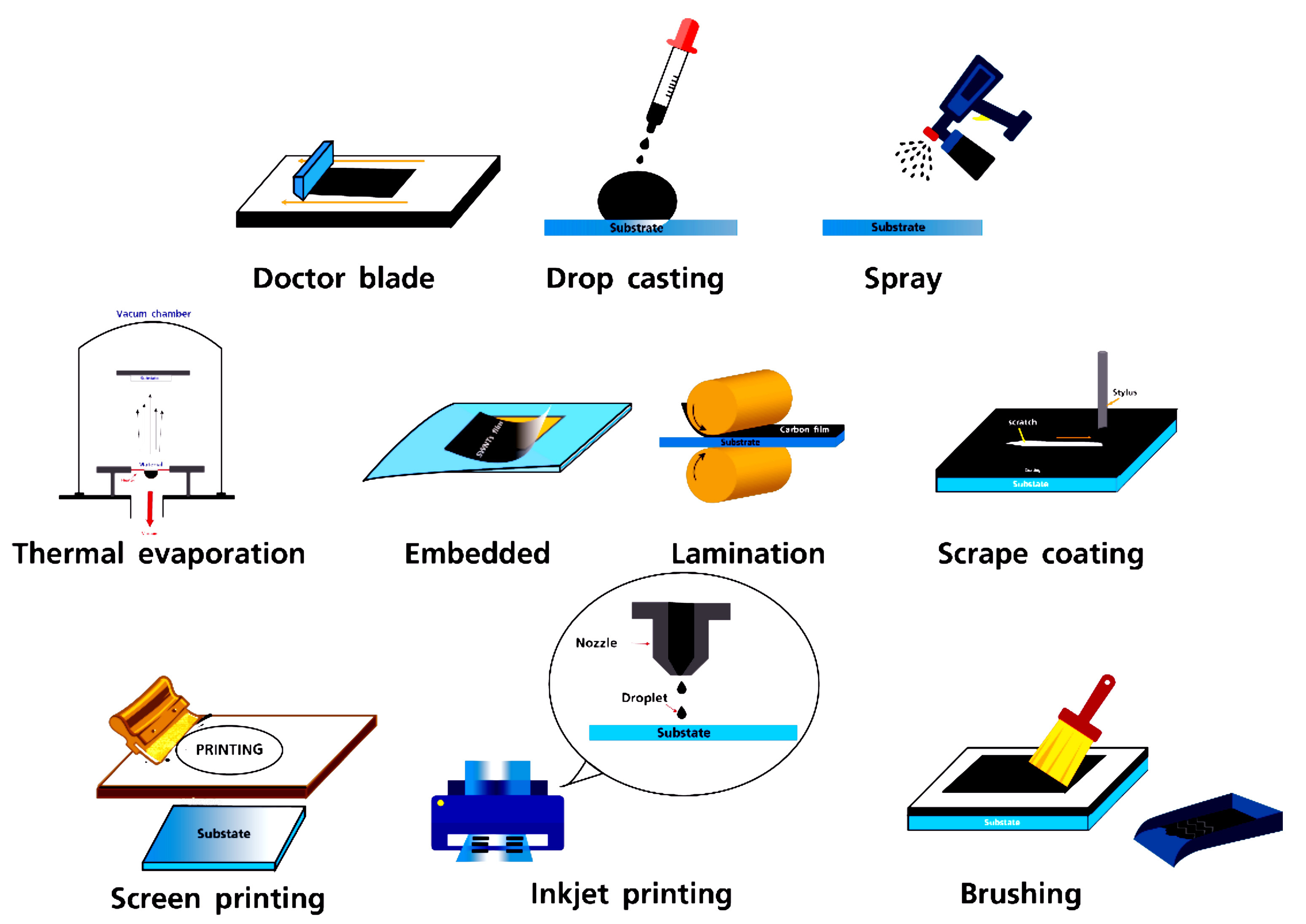
Figure 7. Schematic Illustration of Several Techniques for Fabrication of cCEs in PSC. Reproduced from Ref.[190] with permission from MDPI.
The methods that have been extensively utilized, analyzed, and documented to date are predominantly solution-based and fall under the broader category of printing techniques. Here are a few examples:
1) Screen Printing: Screen printing involves depositing ink onto a surface using a mesh that selectively blocks certain areas to prevent ink from passing through. A stencil is created on the mesh screen using a blade, which then applies pressure to transfer the ink, reproducing the design on the underlying surface. This technique is commonly used in manufacturing screen-printed electrodes[191]. In the context of C-PSMs, screen printing is frequently employed to sequentially apply the mesoporous TiO2 layer, the ZrO2 layer, and the carbon layer in the HT triple mesoscopic structure.
2) Inkjet Printing: Inkjet printing applies ink to a surface without physical contact by precisely controlling the deposition of ink droplets, either continuously or selectively. This method has been effectively used for various printed electronic products, including solar panels, sensors, and transistors. It offers improved environmental performance compared to spin coating, generating minimal waste. For instance, inkjet printing consumes 1.152MJ/m² of energy, while spin coating consumes 1.8MJ/m², indicating a 36% reduction in energy use for inkjet printing[192,193]. In C-PSMs, inkjet printing can be used to deposit the ETL, perovskite ink, and HTL in various device topologies. Additionally, this process can be employed to produce the CE for C-PSMs that utilize LT C paste structures[194].
3) Blade Coating: Blade coating, a technique commonly used in medical and other fields, involves applying a thin liquid layer onto a substrate surface. This is achieved using a mobile blade positioned at a fixed yet adjustable distance from the surface, which evenly distributes the ink. The method is both economical and straightforward, allowing for the creation of films with precise thicknesses. It is widely employed for producing perovskite films on a large scale. In C-PSMs, blade coating can be used to deposit all layers, including the ETL, perovskite layer, HTL, and CE, in both low-temperature and high-temperature device configurations.
4) Slot-Die Coating: Slot-die coating involves directing a precursor ink through a microfluidic metal die positioned close to a moving substrate. This method is highly efficient in terms of material utilization, with minimal waste compared to other techniques. It also offers high-speed capabilities and is suitable for roll-to-roll processing to produce flexible electronics. Slot-die coating is commonly used in the manufacture of organic solar cells and is applicable to C-PSMs for creating the ETL, perovskite, and HTL layers. With appropriate regulation and optimization, this technique can also be used to deposit the C electrode in C-PSMs.
5)Vacuum Deposition: Vacuum deposition involves depositing thin layers of material onto a surface within a vacuum environment. A highly efficient method in constructing PSCs is the alternating layer-by-layer vacuum deposition process, which achieves an average efficiency of 15.37% and demonstrates excellent long-term stability[195].
The deposition procedure consists of two steps: a controlled two-step deposition process involving the reaction of spin-coated PbI₂ and spray-coated CH₃NH₃I under normal atmospheric conditions. This method has achieved a PCE of 11.4% in a device area of 0.04cm²[196]. A straightforward approach for forming perovskite films can produce films with thicknesses exceeding 1μm under normal conditions. This process yields an average PCE of 19.1% and shows consistent results[197].
Manipulation of Structure and Form: By using specific solutions, the morphology of the perovskite film can be manipulated to create dense and well-covered films, which enhances device performance[198]. The spin coating technique is commonly used for the deposition of perovskite. However, it is suboptimal due to practical difficulties when scaling up to large surfaces. This method also generates significant waste materials (up to 95%) and requires a large quantity of hazardous solvents, making it unsuitable for large-area applications or economically viable on a larger scale. While vapor deposition techniques can produce highly homogeneous perovskite films, they necessitate specific vacuum pressures and specialized equipment, which increases operational costs. Currently, the press transfer approach has achieved the highest PCEs in laboratory-scale C-PSCs, as reported in previous studies[14,156,199,200]. However, this method has not yet been employed for devices larger than 1cm².
In this section, we will discuss the most widely used scalable deposition methods for producing high-temperature and low-temperature CEs, as illustrated in Figure 8A-D. The blade-coating or doctor-blading process involves depositing material onto a substrate, whether rigid or flexible, using a blade. By adjusting factors such as the quantity of material, the distance between the meniscus, and the concentration and composition of the precursor solutions, it is possible to achieve highly uniform films. After deposition, an annealing step is necessary, often conducted in a vacuum chamber, to improve solvent binder evaporation efficiency[201]. The screen-printing technique uses a screen with a specific design to apply a substance with precise and regulated thickness. These scalable deposition technologies can be implemented in manufacturing processes such as roll-to-roll[202-205]. Transfer and hot pressing are alternative techniques for producing a single carbon film on a substrate[14,149,155]. These methods bypass the annealing process and preserve the organic HTM or passivating agent on the perovskite surface. In this approach, the carbon film is created through printing processes. It is then detached from the substrate either by solvent exchange or mechanical peeling and applied to the solar device using a press to ensure proper mechanical implementation.
|
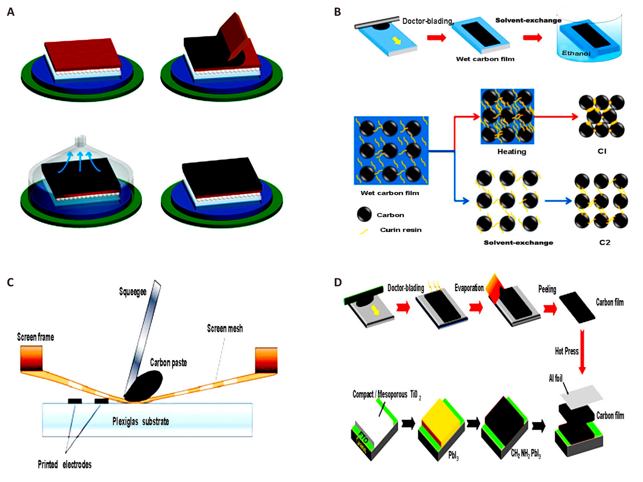
Figure 8. Carbon Film Preparation and Integration into Solar Devices Using Various Techniques. A: Deposition of carbon material, blade coating, and vacuum/heat treatment to fast-dry the film. Reproduced from Ref.[201] with permission from American Chemical Society. B: Solvent exchange is used to obtain the carbon film. Reproduced from Ref.[14] with permission from Wiley-VCH. C: Schematic structure of carbon paste printing with the screen printing technique. Reproduced from Ref.[206] with permission from MDPI. D: Mechanical peeling of carbon film and incorporation into the solar device. Reproduced from Ref.[27] with permission from Elsevier.
Spin-coating, inkjet printing, and spray-coating processes are generally not used to create carbon counter electrodes due to the presence of viscous binders such as ethylene glycol. However, there are various examples in the literature demonstrating competitive efficiency[200,207,208]. Unfortunately, none of the abstracts specifically address the incorporation of carbon into the perovskite layer for creating C-PSCs. As a result, the available abstracts do not provide enough information for a comprehensive response to this query. The fabrication process of C-PSCs can be summarized by the following essential steps: (a) Conventional manufacturing techniques, such as one-step spin coating, two-step deposition, and vapor deposition, have been extensively investigated for laboratory preparation[209,210]. (b) The one-step solution fabrication process is highly convenient for large-scale production and significantly contributes to the advancement of PSCs[211]. (c) Two-step procedures, which involve the transformation of a PbI₂ film into a perovskite film, are frequently used and can yield films with uniform and interconnected structures[212]. (d) The manufacture of PSCs commonly relies on solution-based deposition processes, such as one-step and two-step procedures, which are widely used and prevalent. The hydrophobic characteristics of carbon can enhance the stability of PSC when used as a counter electrode[213]. (e) Researchers have documented the use of a CE operating at low temperatures for creating PSMs. This process is carried out under normal air conditions and controlled using printing methods[214]. In summary, the synergy between novel materials and advanced fabrication techniques has led to significant improvements in the performance and stability of C-PSCs. By optimizing both material properties and manufacturing processes, researchers continue to push the boundaries of what can be achieved in terms of efficiency, scalability, and device longevity.
Addressing the challenges faced by C-PSCs in large-scale manufacturing involves tackling several key areas: technical processes, chemical routes, and stability issues. Firstly, in terms of technical challenges, ensuring uniformity and reproducibility across large areas is crucial. This can be achieved by developing and refining scalable fabrication techniques such as roll-to-roll processing and slot-die coating, which are essential for ensuring uniform layer deposition. Additionally, implementing automated quality control systems will help maintain consistency in large-scale production[215]. For device integration, it is important to create scalable processes that allow C-PSCs to be integrated into flexible substrates or large-area panels. Techniques such as screen printing and inkjet printing need to be adapted for large-scale integration while preserving high efficiency[216]. Secondly, addressing chemical routes involves optimizing material synthesis and processing solvents and additives. For material synthesis, optimizing routes for perovskite precursors is essential to ensure high purity and reproducibility. Advanced chemical methods, including high-throughput screening and automated synthesis platforms, should be utilized to streamline material preparation[92]. Regarding processing solvents and additives, developing stable and environmentally friendly solvents is crucial. This involves optimizing solvent systems to prevent degradation during processing and ensuring their compatibility with large-scale fabrication methods[217]. Thirdly, tackling stability issues involves improving both environmental and long-term stability. To address degradation under environmental conditions, advanced encapsulation technologies should be employed to protect C-PSCs from moisture, oxygen, and UV radiation. Developing durable barrier films and encapsulation layers will enhance the longevity and prevent degradation over time[218]. For the long-term stability of materials, research should focus on developing more stable perovskite compositions and robust carbon-based electrodes. Incorporating stabilizers and protective coatings can significantly enhance the durability of both the perovskite layer and the CE[125]. Additionally, overcoming scaling up challenges involves developing scalable and cost-effective manufacturing techniques that maintain material quality. Techniques such as thermal evaporation and chemical vapor deposition should be optimized for large-scale production while ensuring high efficiency and stability of the C-PSCs[219]. By addressing these areas effectively, the manufacturing process for C-PSCs can be optimized for large-scale production, improving both efficiency and stability.
5.1 Main Challenges of C-PSCs and Possible Strategies
C-PSCs represent a promising area in solar technology due to their lower production costs and inherent material flexibility. However, these PSCs face several significant challenges that hinder their widespread application and commercial viability, including issues related to stability, efficiency, charge transport, and scalability. The first major challenge is limited stability. C-PSCs are more vulnerable to degradation compared to traditional silicon-based solar cells. Factors such as exposure to moisture, oxygen, and UV radiation can cause the perovskite layer and the CE to deteriorate, leading to a significant reduction in efficiency over time[185]. To address this, researchers are focusing on improving encapsulation techniques. Advanced encapsulation can protect the solar cells from environmental exposure, with barrier layers and hermetic seals emerging as effective solutions for prolonging the lifespan of PSCs[220]. Additionally, efforts to enhance the materials themselves by developing more stable perovskite compositions and carbon-based electrodes are also showing promise. These material modifications aim to make the perovskite layer more resistant to environmental degradation, thus enhancing the stability of the device[221]. Another significant issue is lower efficiency. C-PSCs typically exhibit lower PCE compared to metal-electrode-based counterparts. This shortfall is largely due to the less effective charge transport and collection properties of CEs[222]. Researchers are working on optimizing the CE itself to address this issue. By incorporating advanced materials like graphene or CNTs, the charge transport and collection properties of CEs can be significantly enhanced, potentially leading to higher efficiency[125]. Furthermore, improvements in the interface between the perovskite layer and the CE are crucial. Modifying or engineering the interface with specialized interfacial layers can help reduce recombination losses, a key factor contributing to efficiency reductions[223]. A third challenge is inefficient charge transport. The conductivity of carbon materials is generally lower than that of metals, which can result in charge carrier losses and poor charge transport in C-PSCs[224]. To overcome this, efforts are being directed towards enhancing the electronic properties of carbon materials. Researchers are exploring the use of doped carbon black or hybrid carbon composites, which demonstrate improved conductivity and thus can facilitate better charge transport[225]. Additionally, optimizing the cell architecture by designing better layer structures or integrating conductive additives can help ensure more efficient charge collection and transport within the solar cell[225]. Fourthly, scalability and manufacturing pose considerable hurdles. Large-scale production of C-PSCs faces numerous technical challenges, such as ensuring uniformity and reproducibility while maintaining cost-effectiveness[226]. To address these scalability issues, researchers are focusing on developing fabrication techniques that can be easily scaled. For example, roll-to-roll processing and inkjet printing have shown potential as cost-effective and scalable methods for manufacturing PSCs[215]. At the same time, stringent quality control measures are essential for ensuring uniformity and reliability across large production batches. Implementing comprehensive testing procedures during manufacturing could help achieve the necessary consistency and durability for commercial applications[227].
6 CONCLUSION AND FUTURE PROSPECTS
The use of CEs in PSMs has clearly demonstrated its potential to advance this technology towards commercialization. This potential is highlighted by the increasing number of academic publications on the subject over the past seven years. Although the effectiveness of C-PSMs has been established, significant challenges remain in improving both PCE and stability, and in ensuring the economic viability of C-PSMs as commercial products. Key areas requiring further scrutiny and enhancement include uniformity in film production. Achieving uniform films on a larger scale is a major challenge when scaling up C-PSCs structures. The reduction in PCE when transitioning from single solar cells to modules presents a significant barrier to commercialization. The difficulty is compounded by the challenge of obtaining uniform coatings over large surfaces using industrially viable and cost-effective processes, such as printing. The perovskite layer, which greatly impacts device performance, is a primary concern. Research should focus on refining deposition and annealing processes to produce higher quality films under typical environmental conditions. Scaling up and managing production techniques for high-quality perovskite films is essential for successful commercialization. An analysis of two-step techniques for creating effective and durable PSMs highlights the promising prospects of two-step vapor-based approaches for efficient and continuous manufacturing[228].
6.1 Challenges and Limitations in the Fabrication of C-PSCs
(a) Low-Temperature Processing: Fabricating C-PSCs at extremely low temperatures remains a significant challenge, negatively impacting cell efficiency[229]. (b) Perovskite Infiltration Inconsistency: Irregularities in the infiltration of perovskite material into micrometer-thick mesoscopic devices present difficulties in C-PSC production. (c) Sensitivity to Moisture: Protruding perovskite crystals in C-PSCs can undergo hydrolysis in humid environments, accelerating degradation[230]. (d) Device Stability: While C-PSCs exhibit enhanced stability compared to traditional PSCs, issues related to long-term durability and thermal stability persist[229,230].
6.2 Main Challenges in Scaling Up the Production Process of C-PSCs
(a) Manufacturing Large-Scale Items: Developing effective techniques for producing large-area perovskite modules is essential for scaling up to terawatt-level production[231-235]. Blade coating, slot-die coating, and spray coating are solution deposition processes that support continuous roll-to-roll or sheet-to-sheet processing, making them suitable for large-scale production[231-233]. (b) Chemical Routes and Stability: Developing safer chemical methods for PSC production is crucial for commercialization[231,232,236,237]. Addressing stability issues such as module stability, potential lead leakage, and field testing for large-area PSCs is necessary[232,235,236,238]. (c) Carbon-Based Materials: Carbon materials are highly promising for addressing stability concerns in photovoltaic devices due to their excellent properties, including moisture resistance and improved stability of PSCs[230,236,237]. Unfortunately, none of the current presentations specifically address the distinct challenges associated with scaling the manufacturing process of C-PSCs. From the available data, it can be concluded that the commercialization of C-PSCs hinges on overcoming key issues related to large-scale manufacturing, chemical processes, and stability concerns. Further research in these areas is critical to addressing these challenges and enabling the successful scaling of production. Moreover, the application of chemical modifications and custom engineering techniques strategies that have demonstrated their effectiveness in other types of thin-film solar technologies could also aid in overcoming these challenges. To enhance the performance of C-PSMs, it is essential to achieve uniform and well-organized charge extraction and perovskite layers. Such improvements could enable C-PSMs to reach PCEs comparable to those of silicon-based photovoltaic modules. Additionally, C-PSMs offer the advantage of significantly lower production costs, making them a more cost-effective alternative[239].
Optimizing interfacility engineering is crucial for enhancing performance in solar module production. During the scale-up process, the method of connecting cells, typically achieved through scribing, plays a significant role in determining the geometric fill factor, which is a key parameter in solar module manufacturing. Laser scribing, in contrast to mechanical scribing, has emerged as a highly promising technique. This method is particularly efficient when combined with the monolithic fabrication of modules using techniques like screen printing. By incorporating the latest laser technology from electronics manufacturing, the scribing process can be improved, resulting in higher fill factor values and increased PCE, while simultaneously reducing the losses typically associated with scaling up. Another critical aspect in the production of C-PSMs is encapsulation, which is essential for protecting the modules from potential damage caused by environmental and mechanical factors. Implementing effective encapsulation techniques and using durable materials can extend the lifespan of C-PSMs to up to ten years, making them comparable to the lifespan of current solar modules available in the market. However, a thorough investigation is necessary due to the intricate composition of C-PSMs, which consist of multiple layers, each responding differently to changes in temperature and chemical exposure. The perovskite layer, in particular, is highly susceptible to degradation. Addressing these challenges would pave the way for solar systems with integrated energy storage capabilities to successfully enter the market in the near future. Carbon materials offer several advantages in overcoming these obstacles. First, their hydrophobic properties help protect perovskite films from moisture, thereby enhancing the stability of the modules[236,237]. Second, carbon materials contribute to the thermal stability of C-PSCs, improving their long-term durability[236]. Lastly, the fabrication of C-PSCs is cost-effective, making them an attractive option for commercialization, despite the challenges that remain[237,240].
C-PSCs present several advantages over traditional silicon-based solar cells and other commercial technologies. Although their efficiency is currently lower than the highest-performing silicon cells, these advantages make them a compelling alternative: Firstly, C-PSCs are generally more cost-effective than silicon-based solar cells due to the lower cost of raw materials and simpler fabrication processes. The manufacturing of C-PSCs can utilize cost-effective techniques such as roll-to-roll printing and solution processing, which significantly reduce production expenses compared to the high-cost, energy-intensive processes required for silicon wafers. Recent studies confirm this cost advantage, demonstrating that C-PSCs can be produced at a fraction of the cost of silicon-based counterparts[226]. Secondly, one of the significant benefits of C-PSCs is their flexibility and lightweight nature. These characteristics make them suitable for a wide range of applications, including integration into flexible substrates, wearable devices, and unconventional surfaces such as curved or portable structures. This flexibility allows for innovative applications that traditional, rigid silicon cells cannot accommodate. Recent research highlights how the flexibility of C-PSCs enables their use in novel applications and configurations[241]. Thirdly, C-PSCs can be manufactured using scalable and versatile methods such as inkjet printing, spray coating, and roll-to-roll processing. These methods facilitate large-scale production at lower costs and with reduced environmental impact. In contrast, the production of silicon solar cells involves complex and expensive fabrication processes, including high-temperature processing and precision equipment. Recent advancements in scalable manufacturing techniques for C-PSCs have been documented, showcasing their potential for cost-effective, high-volume production[90]. Fourthly, Perovskite materials are known for their excellent light absorption properties due to their broad absorption spectrum and high extinction coefficient. This enables C-PSCs to capture more of the solar spectrum compared to silicon cells. The ability to achieve high absorption with thinner layers improves the overall material efficiency. Recent studies have demonstrated that perovskite materials can outperform silicon in terms of light absorption efficiency, making them a promising candidate for next-generation solar technologies[242]. Fifthly, while C-PSCs currently exhibit lower efficiencies compared to the best silicon cells, their potential for high efficiency is significant. Ongoing advancements in perovskite materials, interface engineering, and device architecture are continually pushing their performance closer to, and potentially beyond, that of silicon-based cells. Recent research highlights that C-PSCs have shown rapid improvements in efficiency and have the potential to surpass silicon cells as further developments are made[243].
In conclusion, while C-PSCs present key advantages such as low-cost fabrication and enhanced stability, several challenges must be overcome to enable their widespread commercialization. These challenges primarily include issues related to low-temperature processing, moisture sensitivity, and long-term device stability[229,230,236,237,240]. Exploring interface engineering in C-PSCs presents a significant opportunity to improve both the stability and efficiency of these renewable energy devices. Throughout our discussion, we examined various aspects of C-PSCs. We began by addressing the environmental risks associated with these cells, followed by a detailed assessment of the factors influencing material costs. Additionally, we highlighted the crucial role of interfacial properties in determining the overall performance of C-PSCs. These findings underscore the intricate interactions that define C-PSCs technology, demonstrating the need to address environmental concerns and optimize material costs in order to enhance the efficiency and longevity of solar energy devices. Furthermore, fabrication processes were a central theme, with a particular focus on how efficiency can be improved through the optimization of manufacturing methods and interface engineering. The multifaceted approach to enhancing efficiency illustrates the delicate balance required to achieve optimal performance in C-PSCs[244-246].
The review analyzed key factors influencing the stability of PSCs, including exposure to moisture, oxygen, light, thermal stress, and their combined effects under atmospheric conditions. The solutions presented in this document provide a comprehensive overview of how interfacial engineering can effectively mitigate the stability challenges posed by environmental factors. The discussion focused on both the existing barriers and the future prospects within the field of PSCs, underscoring the importance of ongoing research and technological innovation. Given the rapidly evolving nature of PSC technology, sustained efforts are required to overcome current challenges and develop sustainable, high-performance solutions. In essence, prioritizing interface engineering emerges as a pivotal strategy for improving PSCs, offering an in-depth understanding of the interplay between materials, fabrication processes, and stability concerns. This investigation significantly contributes to the broader discourse surrounding renewable energy technologies, advancing the goal of making solar energy more efficient and dependable.
Acknowledgements
The authors acknowledged the Tianchi Talent Project of Xinjiang Uygur Autonomous Region (No. CZ000914 and No. CZ000901), the Start-up Project of Shihezi University (No. KX6086), International Cooperation Project of Shihezi University (No. GJHZ202408) and the K.C.Wong Education Foundation, Hong Kong (No. FZ0013). Special thanks to Prof. Juan Hou for her invaluable assistance on Ibrahim Albrahee’s living and study in China. Thanks so much for the support from Prof. Guichuan Xing on Prof. Yang Li’s research during these years.
Conflicts of Interest
The authors declared no conflicts of interest.
Data Availability
Data sharing is not applicable to this review as no datasets were generated or analyzed during the current study.
Copyright Permissions
Copyright © 2025 The Author(s). Published by Innovation Forever Publishing Group Limited. This open-access article is licensed under a Creative Commons Attribution 4.0 International License (https://creativecommons.org/licenses/by/4.0), which permits unrestricted use, sharing, adaptation, distribution, and reproduction in any medium, provided the original work is properly cited.
Author Contribution
Albrahee I and Li Y deliberated and put up the concept of the paper. Albrahee I authored the primary manuscript. Li Y critically examined and revised the work and edited and oversaw the primary manuscript text and writing. All authors have reviewed and consented to the final version of the manuscript that has been published.
Abbreviation List
2D, Two-dimensional
C₆₀, Fullerene
CE, Carbon electrode
CNDs, Carbon nanodots
CNTs, Carbon nanotubes
COFs, Covalent organic frameworks
CPE, Carbon paste electrodes
C-PSCs, Carbon-based PSCs
DI, Deionized
ETL, Electron transport layer
G-C3N4, Graphitic carbon nitride
GO, Graphene oxide
HOFs, Hydrogen-bonded organic frameworks
HTLs, Hole transport layers
HTMs, Hole transport materials
I-PSCs, Inverted PSCs
MPP, Maximum power point
MWCNTs, Multi-walled CNTs
N-PSCs, Normal PSCs
PCBM, Phenyl-C₆₁-butyric acid methyl ester
PCEs, Power conversion efficiencies
PEI, Polyethyleneimine
PSCs, Perovskite solar cells
PSMs, Perovskite solar modules
QDs, Quantum dots
RH, Relative humidity
SAMs, Self-assembled molecules
TFMS, Trifluoromethanesulfonic
WF, Work function
References
[1] Kojima A, Teshima K, Shirai Y et al. Organometal halide perovskites as visible-light sensitizers for photovoltaic cells. J Am Chem Soc, 2009; 131: 6050-6051.[DOI]
[2] Min H, Lee DY, Kim J et al. Perovskite solar cells with atomically coherent interlayers on SnO2 electrodes. Nature, 2021; 598: 444-450.[DOI]
[3] Park J, Kim J, Yun HS et al. Controlled growth of perovskite layers with volatile alkylammonium chlorides. Nature, 2023; 616: 724-730.[DOI]
[4] Zhao Y, Ma F, Qu Z et al. Inactive (PbI2) 2RbCl stabilizes perovskite films for efficient solar cells. Science, 2022; 377: 531-534.[DOI]
[5] Shao JY, Li D, Shi J et al. Recent progress in perovskite solar cells: material science. Sci China Chem, 2023; 66: 10-64.[DOI]
[6] Rong Y, Hu Y, Mei A et al. Challenges for commercializing perovskite solar cells. Science, 2018; 361: eaat8235.[DOI]
[7] Zhang T, Wang F, Kim HB et al. Ion-modulated radical doping of spiro-OMeTAD for more efficient and stable perovskite solar cells. Science, 2022; 377: 495-501.[DOI]
[8] Li X, Zhang W, Guo X et al. Constructing heterojunctions by surface sulfidation for efficient inverted perovskite solar cells. Science, 2022; 375: 434-437.[DOI]
[9] Wu S, Chen R, Zhang S et al. A chemically inert bismuth interlayer enhances long-term stability of inverted perovskite solar cells. Nat Commun, 2019; 10: 1161.[DOI]
[10] Tan S, Yavuz I, Huang T et al. Steric impediment of ion migration contributes to improved operational stability of perovskite solar cells. Adv Mater, 2020; 32: 1906995.[DOI]
[11] Rajagopal A, Yao K, Jen AKY. Toward perovskite solar cell commercialization: a perspective and research roadmap based on interfacial engineering. Adv Mater, 2018; 30: 1800455.[DOI]
[12] Zhang C, Liang S, Liu W et al. Ti1-graphene single-atom material for improved energy level alignment in perovskite solar cells. Nat Energy, 2021; 6: 1154-1163.[DOI]
[13] Wang Y, Li W, Yin Y et al. Defective MWCNT Enabled Dual Interface Coupling for Carbon‐Based Perovskite Solar Cells with Efficiency Exceeding 22%. Adv Funct Mater, 2022; 32: 2204831.[DOI]
[14] Zhang H, Xiao J, Shi J et al. Self‐adhesive macroporous carbon electrodes for efficient and stable perovskite solar cells. Adv Funct Mater, 2018; 28: 1802985.[DOI]
[15] Xiang J, Han C, Qi J et al. A Polymer Defect Passivator for Efficient Hole‐Conductor‐Free Printable Mesoscopic Perovskite Solar Cells. Adv Funct Mater, 2023; 33: 2300473.[DOI]
[16] Mei A, Sheng Y, Ming Y et al. Stabilizing perovskite solar cells to IEC61215: 2016 standards with over 9,000-h operational tracking. Joule, 2020; 4: 2646-2660.[DOI]
[17] Zhang J, Duan J, Guo Q et al. A Universal Grain “Cage” to Suppress Halide Segregation of Mixed-Halide Inorganic Perovskite Solar Cells. ACS Energy Lett, 2022; 7: 3467-3475.[DOI]
[18] Ye T, Hou Y, Nozariasbmarz A et al. Cost-Effective High-Performance Charge-Carrier-Transport-Layer-Free Perovskite Solar Cells Achieved by Suppressing Ion Migration. ACS Energy Lett, 2021; 6: 3044-3052.[DOI]
[19] Tian T, Zhong JX, Yang M et al. Interfacial Linkage and Carbon Encapsulation Enable Full Solution‐Printed Perovskite Photovoltaics with Prolonged Lifespan. Angew Chem Int Edit, 2021; 60: 23735-23742.[DOI]
[20] Liao Y, Zhang J, Wang W et al. Anti‐Dissociation Passivation via Bidentate Anchoring for Efficient Carbon‐Based CsPbI2. 6Br0. 4 Solar Cells. Adv Funct Mater, 2023; 33: 2214784.[DOI]
[21] Wang Y, Li L, Wu Z et al. Self‐Driven Prenucleation‐Induced Perovskite Crystallization Enables Efficient Perovskite Solar Cells. Angew Chem Int Edit, 2023; 62: e202302342.[DOI]
[22] Guo Q, Duan J, Zhang J et al. Universal dynamic liquid interface for healing perovskite solar cells. Adv Mater, 2022; 34: 2202301.[DOI]
[23] Du J, Duan J, Yang X et al. p‐Type Charge Transfer Doping of Graphene Oxide with (NiCo) 1- yFeyOx for Air‐Stable, All‐Inorganic CsPbIBr2 Perovskite Solar Cells. Angew Chem Int Edit, 2021; 60: 10608-10613.[DOI]
[24] Tian C, Mei A, Zhang S et al. Oxygen management in carbon electrode for high-performance printable perovskite solar cells. Nano Energy, 2018; 53: 160-167.[DOI]
[25] Li H, Cao K, Cui J et al. 14.7% efficient mesoscopic perovskite solar cells using single walled carbon nanotubes/carbon composite counter electrodes. Nanoscale, 2016; 8: 6379-6385.[DOI]
[26] Yang Y, Xiao J, Wei H et al. An all-carbon counter electrode for highly efficient hole-conductor-free organo-metal perovskite solar cells. RSC Adv, 2014; 4: 52825-52830.[DOI]
[27] Wei H, Xiao J, Yang Y et al. Free-standing flexible carbon electrode for highly efficient hole-conductor-free perovskite solar cells. Carbon, 2015; 93: 861-868.[DOI]
[28] Jiang P, Jones TW, Duffy NW et al. Fully printable perovskite solar cells with highly-conductive, low-temperature, perovskite-compatible carbon electrode. Carbon, 2018; 129: 830-836.[DOI]
[29] Liu Z, Sun B, Shi T et al. Enhanced photovoltaic performance and stability of carbon counter electrode based perovskite solar cells encapsulated by PDMS. J Mat Chem A, 2016; 4: 10700-10709.[DOI]
[30] Zhou H, Shi Y, Dong Q et al. Hole-conductor-free, metal-electrode-free TiO2/CH3NH3PbI3 heterojunction solar cells based on a low-temperature carbon electrode. J Phys Chem Lett, 2014; 5: 3241-3246.[DOI]
[31] Zheng X, Chen H, Wei Z et al. High-performance, stable and low-cost mesoscopic perovskite (CH3NH3PbI3) solar cells based on poly (3-hexylthiophene)-modified carbon nanotube cathodes. Front Optoelectron, 2016; 9: 71-80.[DOI]
[32] Zheng X, Chen H, Li Q et al. Boron doping of multiwalled carbon nanotubes significantly enhances hole extraction in carbon-based perovskite solar cells. Nano lett, 2017; 17: 2496-2505.[DOI]
[33] Mali S, Kim H, Patil JV et al. Bio-inspired carbon hole transporting layer derived from aloe vera plant for cost-effective fully printable mesoscopic carbon perovskite solar cells. ACS Appl Mater Inter, 2018; 10: 31280-31290.[DOI]
[34] Meng F, Gao L, Yan Y et al. Ultra-low-cost coal-based carbon electrodes with seamless interfacial contact for effective sandwich-structured perovskite solar cells. Carbon, 2019; 145: 290-296.[DOI]
[35] Zhang N, Guo Y, Yin X et al. Spongy carbon film deposited on a separated substrate as counter electrode for perovskite-based solar cell. Mater Lett, 2016; 182: 248-252.[DOI]
[36] Wei Z, Yan K, Chen H et al. Cost-efficient clamping solar cells using candle soot for hole extraction from ambipolar perovskites. Energ Environ Sci, 2014; 7: 3326-3333.[DOI]
[37] Liu K, Yang P, Li S et al. Induced potential in porous carbon films through water vapor absorption. Angew Chem Int Edit, 2016; 55: 8003-8007.[DOI]
[38] Ding T, Liu K, Li J et al. All‐printed porous carbon film for electricity generation from evaporation‐driven water flow. Adv Funct Mater, 2017; 27: 1700551.[DOI]
[39] Liu Z, Liu C, Chen C et al. Recent advances in two‐dimensional materials for hydrovoltaic energy technology. Exploration, 2023; 3: 20220061.[DOI]
[40] Zhang X, Gao N, Li Y et al. A Solution-Processed Dopant-Free Tin Phthalocyanine (SnPc) Hole Transport Layer for Efficient and Stable Carbon-Based CsPbI2Br Planar Perovskite Solar Cells Prepared by a Low-Temperature Process. ACS Appl Energ Mater, 2020; 3: 7832-7843.[DOI]
[41] Wang H, Liu H, Li W et al. Inorganic perovskite solar cells based on carbon electrodes. Nano Energy, 2020; 77: 105160.[DOI]
[42] Chen H, Yang S. Methods and strategies for achieving high-performance carbon-based perovskite solar cells without hole transport materials. J Mater Chem A, 2019; 7: 15476-15490.[DOI]
[43] Chen H, Yang S. Carbon‐based perovskite solar cells without hole transport materials: The front runner to the market? Adv Mater, 2017; 29: 1603994.[DOI]
[44] Choubey A, Perumal N, Muthu SP et al. Ambient-air fabrication of efficient and stable carbon-based inorganic perovskite solar cell based on CsPbIBr2 film via organic salt passivation. Solar Energy, 2022; 245: 265-277.[DOI]
[45] Meng F, Liu A, Gao L et al. Current progress in interfacial engineering of carbon-based perovskite solar cells. J Mater Chem A, 2019; 7: 8690-8699.[DOI]
[46] Deng F, Li X, Lv X et al. Low-temperature processing all-inorganic carbon-based perovskite solar cells up to 11.78% efficiency via alkali hydroxides interfacial engineering. Acs Appl Energ Mater, 2019; 3: 401-410.[DOI]
[47] Zhong H, Li W, Huang Y et al. All-inorganic perovskite solar cells with tetrabutylammonium acetate as the buffer layer between the SnO2 electron transport film and CsPbI3. Acs Appl Mater Inter, 2022; 14: 5183-5193.[DOI]
[48] Zhou Q, Duan J, Wang Y et al. Tri-functionalized TiOxCl4-2x accessory layer to boost efficiency of hole-free, all-inorganic perovskite solar cells. J Energy Chem, 2020; 50: 1-8.[DOI]
[49] Guo Z, Teo S, Xu Z et al. Achievable high V oc of carbon based all-inorganic CsPbIBr2 perovskite solar cells through interface engineering. J Mater Chem A, 2019; 7: 1227-1232.[DOI]
[50] Zhu W, Chai W, Zhang Z et al. Interfacial TiO2 atomic layer deposition triggers simultaneous crystallization control and band alignment for efficient CsPbIBr2 perovskite solar cell. Org Electron, 2019; 74: 103-109.[DOI]
[51] Qi X, Wang J, Tan F et al. Interfaces, Quantum Dot Interface-Mediated CsPbIBr2 Film Growth and Passivation for Efficient Carbon-Based Solar Cells. ACS Appl Mater Inter, 2021; 13: 55349-55357.[DOI]
[52] Zhou Q, Duan J, Yang X et al. Interfacial strain release from the WS2/CsPbBr3 van der Waals heterostructure for 1.7V voltage all‐inorganic perovskite solar cells. Angew Chem, 2020; 132: 22181-22185.[DOI]
[53] Yang Y, Chen H, Hu C et al. Polyethyleneimine-functionalized carbon nanotubes as an interlayer to bridge perovskite/carbon for all inorganic carbon-based perovskite solar cells. J Mater Chem A, 2019; 7: 22005-22011.[DOI]
[54] Yan F, Yang P, Li J et al. Healing soft interface for stable and high-efficiency all-inorganic CsPbIBr2 perovskite solar cells enabled by S-benzylisothiourea hydrochloride. Chem Eng J, 2022; 430: 132781.[DOI]
[55] Zhang J, Duan J, Zhang Q et al. Understanding steric-charge-dependence of conjugated passivators on π-Pb2+ bond strength for efficient all-inorganic perovskite solar cells. Chem Eng J, 2022; 431: 134230.[DOI]
[56] Zhu J, Liu Y, He B et al. Efficient interface engineering of N, N'-Dicyclohexylcarbodiimide for stable HTMs-free CsPbBr3 perovskite solar cells with 10.16%-efficiency. Chem Eng J, 2022; 428: 131950.[DOI]
[57] Li J, Yan F, Yang P et al. Suppressing interfacial shunt loss via functional polymer for performance improvement of lead‐free Cs2AgBiBr6 double perovskite solar cells. Sol RRL, 2022; 6: 2100791.[DOI]
[58] Zhang X, Zhou Y, Li Y et al. Efficient and carbon-based hole transport layer-free CsPbI2 Br planar perovskite solar cells using PMMA modification. J Mater Chem C, 2019; 7: 3852-3861.[DOI]
[59] Ding Y, He B, Zhu J et al. Advanced Modification of Perovskite Surfaces For Defect Passivation And Efficient Charge Extraction in Air-Stable CsPbBr3 Perovskite Solar Cells. ACS Sustain Chem Eng, 2019; 7: 19286-19294.[DOI]
[60] Han Q, Yang S, Wang L et al. A double perovskite participation for promoting stability and performance of Carbon-Based CsPbI2Br perovskite solar cells. J Colloid Interf Sci, 2022; 606: 800-807.[DOI]
[61] Xu Y, Li G, Li R et al. PbS/CdS heterojunction thin layer affords high-performance carbon-based all-inorganic solar cells. Nano Energy, 2022; 95: 106973.[DOI]
[62] Yuan H, Zhao Y, Duan J et al. All-inorganic CsPbBr3 perovskite solar cell with 10.26% efficiency by spectra engineering. J Mater Chem A, 2018; 6: 24324-24329.[DOI]
[63] Zhao Y, Xu H, Wang Y et al. 10.34%-efficient integrated CsPbBr3/bulk-heterojunction solar cells. J Power Sources, 2019; 440: 227151.[DOI]
[64] Tong G, Chen T, Li H et al. High efficient hole extraction and stable all‐bromide inorganic perovskite solar cells via derivative‐phase gradient bandgap architecture. Sol RRL, 2019; 3: 1900030.[DOI]
[65] Gong S, Li H, Chen Z et al. CsPbI2Br Perovskite Solar Cells Based on Carbon Black-Containing Counter Electrodes. ACS Appl Mater Inter, 2020; 12: 34882-34889.[DOI]
[66] Yin R, Wang K, Cui S et al. Dual-Interface Modification with BMIMPF6 for High-Efficiency and Stable Carbon-Based CsPbI2Br Perovskite Solar Cells. ACS Appl Energ Mater, 2021; 4: 9294-9303.[DOI]
[67] Duan J, Zhao Y, He B et al. Simplified perovskite solar cell with 4.1% efficiency employing inorganic CsPbBr3 as light absorber. Small, 2018; 14: 1704443.[DOI]
[68] Zhao Y, Duan J, Yuan H et al. Using SnO2 QDs and CsMBr3 (M = Sn, Bi, Cu) QDs as Charge-Transporting Materials for 10.6%-Efficiency All-Inorganic CsPbBr3 Perovskite Solar Cells with an Ultrahigh Open-Circuit Voltage of 1.610 V. Sol RRL, 2019; 3: 1800284.[DOI]
[69] Fu H, Zhang J, Li Y et al. A facile interface engineering method to improve the performance of FTO/ZnO/CsPbI3-xBrx (x<1)/C solar cells. J Mater Sci-Mater Electron, 2022; 33: 3711-3725.[DOI]
[70] Zhang W, Zhang Z, Jiang Q et al. Charge-transporting-layer-free, vacuum-free, all-inorganic CsPbIBr2 perovskite solar cells via dipoles-adjusted interface. Nanomaterials, 2020; 10: 1324.[DOI]
[71] Guo R, Zhao Y, Deng Q et al. Energy level matching between transparent conducting electrodes and the electronic transport layer to enhance performance of all-inorganic CsPbBr3 solar cells. Vacuum, 2022; 200: 111028.[DOI]
[72] Planes E, Farha C, De Moor G et al. Maturing Effects in Carbon‐Based Perovskite Solar Cells: Understanding and Consequences on Photovoltaic Performances. Sol RRL, 2023; 7: 2300492.[DOI]
[73] Chen C, Bala H, Yao S et al. Enhanced efficiency and stability of perovskite solar cells based on carbon-counter-electrode via anti-solvent treatment. J Alloy Compd, 2022; 920: 165874.[DOI]
[74] Wang Y, Xie C, Yao X et al. Improved comprehensive performance of CsPbI2Br perovskite solar cells by modifying the photoactive layers with carbon nanodots. J Materiomics, 2022; 8: 358-365.[DOI]
[75] Lu H, Guo X, Yang C et al. Tailoring perovskite compounds for broadband light absorption: Proceedings of the IOP Conference Series: Materials Science and Engineering. Kuala Lumpur, Malaysia, 28-30 November 2017.[DOI]
[76] Niu YC, Yang LF, Aldamasy M et al. Efficient application of carbon-based nanomaterials for high-performance perovskite solar cells. Rare Met, 2021; 40: 2747-2762.[DOI]
[77] Nurzhanov M, Mathur A, Li Y et al. Dicyanobenzene passivated perovskite solar cells with enhanced efficiency and stability. J Mater Chem C, 2023; 11: 15881-15891.[DOI]
[78] Li R, Liu X, Chen J. Opportunities and challenges of hole transport materials for high‐performance inverted hybrid‐perovskite solar cells. Exploration, 2023; 3: 20220027.[DOI]
[79] Ndlovu S, Ollengo MA, Muchuweni E et al. Current advances in perovskite oxides supported on graphene-based materials as interfacial layers of perovskite solar cells. Crit Rev Solid State, 2023; 48: 112-131.[DOI]
[80] Krahne R, Lin ML, Tan P. Interplay of Phonon Directionality and Emission Polarization in Two-Dimensional Layered Metal Halide Perovskites. Accounts Chem Res, 2024; 57: 2476-2489.[DOI]
[81] Syed J, Zhang XY, Ding WJ et al. An overview of the current progress of graphitic carbon nitride and its multifunctional applications. J Environ Chem Eng, 2022; 10: 108745.[DOI]
[82] Yildirim O, Bonomo M, Barbero N et al. Application of metal-organic frameworks and covalent organic frameworks as (photo) active material in hybrid photovoltaic technologies. Energies, 2020; 13: 5602.[DOI]
[83] Ding X, Xie Y, Gao Q et al. Hydrogen‐Bonded Organic Frameworks: Structural Design and Emerging Applications. Chem Phy Chem, 2023; 24: e202200742.[DOI]
[84] Park NG, Zhu K. Scalable fabrication and coating methods for perovskite solar cells and solar modules. Nat Rev Mater, 2020; 5: 333-350.[DOI]
[85] Berger E, Bagheri M, Asgari S et al. Recent developments in perovskite-based precursor inks for scalable architectures of perovskite solar cell technology. Sustain Energ Fuels, 2022; 6: 2879-2900.[DOI]
[86] Pandey S, Karakoti M, Bhardwaj D et al. Recent advances in carbon-based materials for high-performance perovskite solar cells: gaps, challenges and fulfillment. Nanoscale Adv, 2023; 5: 1492-1526.[DOI]
[87] Pan H, Shao H, Zhang XL et al. Interface engineering for high-efficiency perovskite solar cells. J Appl Phys, 2021; 129: 130904.[DOI]
[88] Zhang Y, He Z, Xiong J et al. Multi-functional thermal management for efficient and stable inverted perovskite solar cells. J Mater Chem A, 2024; 12: 10369-10384.[DOI]
[89] Alidaei M, Sadrameli SM, Ahmadi V et al. Prolonged Lifetime of Perovskite Solar Cells Using a Moisture-Blocked and Temperature-Controlled Encapsulation System Comprising a Phase Change Material as a Cooling Agent. ACS Omega, 2020; 5: 7106-7114.[DOI]
[90] Li Z, Klein TR, Kim DH et al. Scalable fabrication of perovskite solar cells. Nat Rev Mater, 2018; 3: 1-20.[DOI]
[91] Zhang J, Wu J, Barabash A et al. Science, Precise control of process parameters for > 23% efficiency perovskite solar cells in ambient air using an automated device acceleration platform. Energ Environ Sci, 2024; 17: 5490-5499.[DOI]
[92] Nazir G, Lee SY, Lee JH et al. Stabilization of perovskite solar cells: recent developments and future perspectives. Adv Mater, 2022; 34: 2204380.[DOI]
[93] Kim M, Ham SY, Cheng D et al. Advanced characterization techniques for overcoming challenges of perovskite solar cell materials. Adv Energy Mater, 2021; 11: 2001753.[DOI]
[94] Xu F, Zhang T, Li G et al. Mixed cation hybrid lead halide perovskites with enhanced performance and stability. J Mater Chem A, 2017; 5: 11450-11461.[DOI]
[95] Wang Z, Jiang Y. Advances in perovskite solar cells: film morphology control and interface engineering. J Clean Prod, 2021; 317: 128368.[DOI]
[96] Zhang X, Yu Z, Zhang D et al. Recent Progress of Carbon‐Based Inorganic Perovskite Solar Cells: From Efficiency to Stability. Adv Energy Mater, 2023; 13: 2201320.[DOI]
[97] Wu Z, Liu Z, Hu Z et al. Highly efficient and stable perovskite solar cells via modification of energy levels at the perovskite/carbon electrode interface. Adv Mater, 2019; 31: 1804284.[DOI]
[98] Wu Z, Bi E, Ono LK et al. Passivation strategies for enhancing device performance of perovskite solar cells. Nano Energy, 2023; 108731.[DOI]
[99] Bhattarai S, Das T. Optimization of the perovskite solar cell design to achieve a highly improved efficiency. Opt Mater, 2021; 111: 110661.[DOI]
[100] Kanda H, Shibayama N, Abuhelaiqa M et al. Gradient band structure: high performance perovskite solar cells using poly (bisphenol A anhydride-co-1, 3-phenylenediamine). J Mater Chem A, 2020; 8: 17113-17119.[DOI]
[101] Dong W, Qiao W, Xiong S et al. Surface passivation and energetic modification suppress nonradiative recombination in perovskite solar cells. Nano-Micro Lett, 2022; 14: 108.[DOI]
[102] Ge M, Yang X, Cai B et al. Naphthylmethylamine post-treatment of MAPbI3 perovskite solar cells with simultaneous defect passivation and stability improvement. Sol Energy, 2021; 220: 18-23.[DOI]
[103] Zhu XZ, Wang KL, Wang JG et al. 2D Perovskite Capping Layer Enabling Stable Perovskite Photovoltaics. Sol RRL, 2024; 8: 2301082.[DOI]
[104] Xu T, Zou K, Lv S et al. Interfaces, Efficient and Stable Carbon-Based Perovskite Solar Cells via Passivation by a Multifunctional Hydrophobic Molecule with Bidentate Anchors. ACS Appl Mater Inter, 2021; 13: 16485-16497.[DOI]
[105] Christians JA, Miranda Herrera PA, Kamat PV. Transformation of the excited state and photovoltaic efficiency of CH3NH3PbI3 perovskite upon controlled exposure to humidified air. J Am Chem Soc, 2015; 137: 1530-1538.[DOI]
[106] Leijtens T, Hoke ET, Grancini G et al. Mapping electric field‐induced switchable poling and structural degradation in hybrid lead halide perovskite thin films. Adv Energy Mater, 2015; 5: 1500962.[DOI]
[107] Frost JM, Butler KT, Brivio F et al. Atomistic origins of high-performance in hybrid halide perovskite solar cells. Nano Lett, 2014; 14: 2584-2590.[DOI]
[108] Xu B, Huang J, Kloo L et al. AgTFSI as p‐type dopant for efficient and stable solid‐state dye‐sensitized and perovskite solar cells. Chem Sus Chem, 2014; 7: 3252-3256.[DOI]
[109] Li W, Dong H, Wang L et al. Montmorillonite as bifunctional buffer layer material for hybrid perovskite solar cells with protection from corrosion and retarding recombination. J Mater Chem A, 2014; 2: 13587-13592.[DOI]
[110] Rolston N, Watson BL, Bailie CD et al. Mechanical integrity of solution-processed perovskite solar cells. Extreme Mech Lett, 2016; 9: 353-358.[DOI]
[111] Berhe TA, Su WN, Chen CH et al. Organometal halide perovskite solar cells: degradation and stability. Energ Environ Sci, 2016; 9: 323-356.[DOI]
[112] Leijtens T, Eperon GE, Pathak S et al. Overcoming ultraviolet light instability of sensitized TiO2 with meso-superstructured organometal tri-halide perovskite solar cells. Nat Commun, 2013; 4: 2885.[DOI]
[113] Aristidou N, Sanchez‐Molina I, Chotchuangchutchaval T et al. The role of oxygen in the degradation of methylammonium lead trihalide perovskite photoactive layers. Angewandte Chemie, 2015; 127: 8326-8330.[DOI]
[114] Aristidou N, Eames C, Sanchez-Molina I et al. Fast oxygen diffusion and iodide defects mediate oxygen-induced degradation of perovskite solar cells. Nat Commun, 2017; 8: 15218.[DOI]
[115] Hong Q, Xu R, Jin T et al. Unraveling the light-induced degradation mechanism of CH3NH3PbI3 perovskite films. Org Electron, 2019; 67: 19-25.[DOI]
[116] Charles B, Dillon J, Weber O et al. Understanding the stability of mixed A-cation lead iodide perovskites. J Mater Chem A, 2017; 5: 22495-22499.[DOI]
[117] Li Z, Yang M, Park J et al. Stabilizing perovskite structures by tuning tolerance factor: formation of formamidinium and cesium lead iodide solid-state alloys. Chem Mater, 2016; 28: 284-292.[DOI]
[118] Heiderhoff R, Haeger T, Pourdavoud N et al. Thermal conductivity of methylammonium lead halide perovskite single crystals and thin films: A comparative study. J Phy Chem C, 2017; 121: 28306-28311.[DOI]
[119] Baranwal A, Kanda H, Shibayama N et al. Thermal degradation analysis of sealed perovskite solar cell with porous carbon electrode at 100 C for 7000 h. Energy Technol-Ger, 2019; 7: 245-252.[DOI]
[120] Malinauskas T, Tomkute-Luksiene D, Sens R et al. Enhancing Thermal Stability and Lifetime of Solid-State Dye-Sensitized Solar Cells via Molecular Engineering of the Hole-Transporting Material Spiro-OMeTAD. ACS Appl Mater Inter, 2015; 7: 11107-11116.[DOI]
[121] Matteocci F, Cinà F, Lamanna E et al. Encapsulation for long-term stability enhancement of perovskite solar cells. Nano Energy, 2016; 30: 162-172.[DOI]
[122] Bella F, Griffini G, Correa-Baena J et al. Gerbaldi, Improving efficiency and stability of perovskite solar cells with photocurable fluoropolymers. Science, 2016; 354: 203-206.[DOI]
[123] Grätzel M. The light and shade of perovskite solar cells. Nat Mater, 2014; 13: 838-842.[DOI]
[124] Mei A, Li X, Liu L et al. A hole-conductor–free, fully printable mesoscopic perovskite solar cell with high stability. Science, 2014; 345: 295-298.[DOI]
[125] Fagiolari L, Bella F, Science E. Carbon-based materials for stable, cheaper and large-scale processable perovskite solar cells. Energ Environ Sci, 2019; 12: 3437-3472.[DOI]
[127] Lira-Cantú M. Perovskite solar cells: Stability lies at interfaces. Nat Energy, 2017; 2: 1-3.[DOI]
[128] Zhong Y, Xu L, Li C et al. Needle coke: A predominant carbon black alternative for printable triple mesoscopic perovskite solar cells. Carbon, 2019; 153: 602-608.[DOI]
[129] Liu S, Cao K, Li H et al. Full printable perovskite solar cells based on mesoscopic TiO2/Al2O3/NiO (carbon nanotubes) architecture. Sol Energy, 2017; 144: 158-165.[DOI]
[130] Luo Q, Ma H, Hao F et al. Carbon nanotube based inverted flexible perovskite solar cells with all‐inorganic charge contacts. Adv Funct Mater, 2017; 27: 1703068.[DOI]
[131] Zhang L, Liu T, Liu L et al. The effect of carbon counter electrodes on fully printable mesoscopic perovskite solar cells. J Mater Chem A, 2015; 3: 9165-9170.[DOI]
[132] Phillips C, Al-Ahmadi A, Potts S et al. The effect of graphite and carbon black ratios on conductive ink performance. J Mater Sci, 2017; 52: 9520-9530.[DOI]
[133] Liu S, Huang W, Liao P et al. 17% efficient printable mesoscopic PIN metal oxide framework perovskite solar cells using cesium-containing triple cation perovskite. J Mater Chem A, 2017; 5: 22952-22958.[DOI]
[134] Bashir A, Lew J, Shukla S et al. Cu-doped nickel oxide interface layer with nanoscale thickness for efficient and highly stable printable carbon-based perovskite solar cell. Sol Energy, 2019; 182: 225-236.[DOI]
[135] Hashmi S, Martineau D, Li X et al. Air processed inkjet infiltrated carbon based printed perovskite solar cells with high stability and reproducibility. Adv Mater Technol, 2017; 2: 1600183.[DOI]
[136] Hu Y, Si S, Mei A et al. Stable large‐area (10×10cm2) printable mesoscopic perovskite module exceeding 10% efficiency. Sol RRL, 2017; 1: 1600019.[DOI]
[137] Grancini G, Roldán-Carmona C, Zimmermann I et al. One-Year stable perovskite solar cells by 2D/3D interface engineering. Nat Commun, 2017; 8: 15684.[DOI]
[138] Zhou L, Zuo Y, Mallick T et al. Enhanced efficiency of carbon-based mesoscopic perovskite solar cells through a tungsten oxide nanoparticle additive in the carbon electrode. Sci Rep, 2019; 9: 8778.[DOI]
[139] Bhandari S, Roy A, Ghosh A et al. Performance of WO3-Incorporated Carbon Electrodes for Ambient Mesoscopic Perovskite Solar Cells. ACS Omega, 2019; 5: 422-429.[DOI]
[140] Li F, Xu Y, Chen W et al. Nanotube enhanced carbon grids as top electrodes for fully printable mesoscopic semitransparent perovskite solar cells. J Mater Chem A, 2017; 5: 10374-10379.[DOI]
[141] Gao L, Zhou Y, Meng F et al. Several economical and eco-friendly bio-carbon electrodes for highly efficient perovskite solar cells. Carbon, 2020; 162: 267-272.[DOI]
[142] Chen H, He H, Zheng X et al. Solvent engineering boosts the efficiency of paintable carbon‐based perovskite solar cells to beyond 14%. Adv Energy Mater, 2016; 6: 1502087.[DOI]
[143] Ding J, Zhao Y, Duan J et al. Alloy‐Controlled Work Function for Enhanced Charge Extraction in All‐Inorganic CsPbBr3 Perovskite Solar Cells. Chem Sus Chem, 2018; 11: 1432-1437.[DOI]
[144] Zhang Y, Zhuang X, Zhou K et al. Vibration treated carbon electrode for highly efficient hole-conductor-free perovskite solar cells. Org Electron, 2018; 52: 159-164.[DOI]
[145] Wang Y, Zhao H, Mei Y et al. Carbon Nanotube Bridging Method for Hole Transport Layer-Free Paintable Carbon-Based Perovskite Solar Cells. ACS Appl Mater Inter, 2018; 11: 916-923.[DOI]
[146] Kim J, Lee G, Lee K et al. Fluorine plasma treatment on carbon-based perovskite solar cells for rapid moisture protection layer formation and performance enhancement. Chem Commun, 2020; 56: 535-538.[DOI]
[147] Liu T, Wang Z, Lou L et al. Interfacial Post‐Treatment for Enhancing the Performance of Printable Carbon‐Based Perovskite Solar Cells. Sol RRL, 2020; 4: 1900278.[DOI]
[148] Yan J, Lin S, Qiu X et al. Accelerated hole-extraction in carbon-electrode based planar perovskite solar cells by moisture-assisted post-annealing. Appl Phys Lett, 2019; 114: 103503.[DOI]
[149] Gholipour S, Correa‐Baena J, Domanski K et al. Highly Efficient and Stable Perovskite Solar Cells based on a Low‐Cost Carbon Cloth. Adv Energy Mater, 2016; 6: 1601116.[DOI]
[150] Wei Z, Chen H, Yan K et al. Hysteresis-free multi-walled carbon nanotube-based perovskite solar cells with a high fill factor. J Mater Chem A, 2015; 3: 24226-24231.[DOI]
[151] Luo Q, Ma H, Zhang Y et al. Cross-stacked superaligned carbon nanotube electrodes for efficient hole conductor-free perovskite solar cells. J Mater Chem A, 2016; 4: 5569-5577.[DOI]
[152] Lee J, Jeon I, Lin H et al. Vapor-assisted ex-situ doping of carbon nanotube toward efficient and stable perovskite solar cells. Nano Lett, 2018; 19: 2223-2230.[DOI]
[153] Luo Q, Ma H, Hou Q et al. All‐carbon‐electrode‐based endurable flexible perovskite solar cells. Adv Funct Mater, 2018; 28: 1706777.[DOI]
[154] Zhou Y, Yin X, Zhao X et al. Efficiently Improving The Stability of Inverted Perovskite Solar Cells by Employing Polyethylenimine-Modified Carbon Nanotubes as Electrodes. ACS Appl Mater Inter, 2018; 10: 31384-31393.[DOI]
[155] Wei H, Xiao J, Yang Y et al. Free-standing flexible carbon electrode for highly efficient hole-conductor-free perovskite solar cells. Carbon, 2015; 93: 861-868.[DOI]
[156] Su H, Xiao J, Li Q et al. Carbon film electrode based square-centimeter scale planar perovskite solar cells exceeding 17% efficiency. Mater Sci Semicon Proc, 2020; 107: 104809.[DOI]
[157] Lee J, Jeon I, Lin H et al. Vapor-assisted ex-situ doping of carbon nanotube toward efficient and stable perovskite solar cells. Nano Lett, 2018; 19: 2223-2230.[DOI]
[158] Tian J, Wang J, Xue Q et al. Composition engineering of all‐inorganic perovskite film for efficient and operationally stable solar cells. Adv Funct Mater, 2020; 30: 2001764.[DOI]
[159] Wang F, Bai S, Tress W et al. Defects engineering for high-performance perovskite solar cells. npj Flex Electron, 2018; 2: 22.[DOI]
[160] Bi E, Tang W, Chen H et al. Efficient perovskite solar cell modules with high stability enabled by iodide diffusion barriers. Joule, 2019; 3: 2748-2760.[DOI]
[161] Wang H, Qiang Y, Zheng S et al. Enhanced Efficiency and Stability of Carbon‐Based Perovskite Solar Cells by Eva Interface Engineering. Adv Mater Interfaces, 2022; 9: 2102069.[DOI]
[162] Que M, Zhang B, Chen J et al. Carbon-based electrodes for perovskite solar cells. Mater Adv, 2021; 2: 5560-5579.[DOI]
[163] Abd Mutalib M, Aziz F, Ismail F et al. Towards high performance perovskite solar cells: A review of morphological control and HTM development. Appl Mater Today, 2018; 13: 69-82.[DOI]
[164] Kajal P, Ghosh K, Powar S. Chapter: Manufacturing techniques of perovskite solar cells. In: Applications of Solar Energy. Springer Publisher: Singapore, 2018; 341-364.
[165] Isikgor F, Zhumagali S, Merino L et al. Molecular engineering of contact interfaces for high-performance perovskite solar cells. Nat Rev Mater, 2023; 8: 89-108.[DOI]
[166] Luo Q, Ma H, Hou Q et al. All‐carbon‐electrode‐based endurable flexible perovskite solar cells. Adv Funct Mater, 2018; 28: 1706777.[DOI]
[167] Bogachuk D, Yang B, Suo J et al. Perovskite solar cells with carbon‐based electrodes–quantification of losses and strategies to overcome them. Adv Energy Mater, 2022; 12: 2103128.[DOI]
[168] Anctil A, Beattie M, Case C et al. Status report on emerging photovoltaics. J Photon Energy, 2023; 13: 042301-042301.[DOI]
[169] Teseletso L, Adachi T. Future availability of mineral resources: ultimate reserves and total material requirement. Miner Econ, 2023; 36: 189-206.[DOI]
[170] Pathak P, Yadav A, Padmanaban S. Transition toward emission-free energy systems by 2050: Potential role of hydrogen. Int J Hydrogen Energ, 2023; 48: 9921-9927.[DOI]
[171] Haegel N, Kurtz S. Global progress toward renewable electricity: Tracking the role of solar (version 3). IEEE J Photovolt, 2023; 13: 768-776.[DOI]
[172] Zouhair S, Clegg C, Valitova I et al. Carbon Electrodes for Perovskite Photovoltaics: Interfacial Properties, Meta‐Analysis, and Prospects. Sol RRL, 2024; 8: 2300929.[DOI]
[173] Gong J, Darling S, You F. Perovskite photovoltaics: life-cycle assessment of energy and environmental impacts. Energ Environ Sci, 2015; 8: 1953-1968.[DOI]
[174] Alberola-Borràs J, Baker J, De Rossi F et al. Perovskite photovoltaic modules: life cycle assessment of pre-industrial production process. Science, 2018; 9: 542-551.[DOI]
[175] Ma D, Hao Y, He J et al. Photovoltaic green application of waste toner carbon on fully printable mesoscopic perovskite solar cells. Sol Energy, 2021; 228: 439-446.[DOI]
[176] Liu C, Gao C, Wang W et al. Cellulose‐Based Oxygen‐Rich Activated Carbon for Printable Mesoscopic Perovskite Solar Cells. Sol RRL, 2021; 5: 2100333.[DOI]
[177] Kevin L, Sulistianto J, Poespawati N. Activated carbon as the counter electrode on perovskite solar cells: Proceedings of the 2019 11th International Conference on Information Technology and Electrical Engineering. Pattaya, Thailand, 10-11 October 2019.[DOI]
[178] Li G, Chen H. Manufacturing Cost Analysis of Single‐Junction Perovskite Solar Cells. Sol RRL, 2024; 8: 2400540.[DOI]
[179] Shan X, Wang S, Fu M et al. Precisely preparing lead iodide passivation layer for enhancing the performance of triple cation perovskite solar cells using krypton fluoride excimer laser. J Power Sources, 2023; 555: 232368.[DOI]
[180] Caicedo-Reina M, Pérez-Escribano M, Urieta-Mora J et al. Influence of alkyl chain length on the photovoltaic properties of dithienopyran-based hole-transporting materials for perovskite solar cells. J Mater Chem C, 2023; 11: 8223-8230.[DOI]
[181] Li Z, Sun X, Zheng X et al. Stabilized hole-selective layer for high-performance inverted pin perovskite solar cells. Science, 2023; 382: 284-289.[DOI]
[182] Zhao X, Liu T, Burlingame Q et al. Accelerated aging of all-inorganic, interface-stabilized perovskite solar cells. Science, 2022; 377: 307-310.[DOI]
[183] Čulík P, Brooks K, Momblona C et al. Design and cost analysis of 100 MW perovskite solar panel manufacturing process in different locations. Acs Energy Lett, 2022; 7: 3039-3044.[DOI]
[184] Liu S, Li J, Xiao W et al. Buried interface molecular hybrid for inverted perovskite solar cells. Nature, 2024; 632: 536-542.[DOI]
[185] Kojima A, Teshima K, Shirai Y et al. Organometal halide perovskites as visible-light sensitizers for photovoltaic cells. J Am Chem Soc, 2009; 131: 6050-6051.[DOI]
[186] You J, Hong Z, Yang Y et al. Low-Temperature Solution-Processed Perovskite Solar Cells with High Efficiency and Flexibility. ACS Nano, 2014; 8: 1674-1680.[DOI]
[187] Kohlrausch E, de Vasconcelos Freitas D, da Silva Filho C et al. Advances in Carbon Materials Applied to Carbon‐Based Perovskite Solar Cells. Energy Technol-Ger, 2023; 11: 2200676.[DOI]
[188] Saliba M, Matsui T, Domanski K et al. Incorporation of rubidium cations into perovskite solar cells improves photovoltaic performance. Science, 2016; 354: 206-209.[DOI]
[189] Soto-Montero T, Soltanpoor W, Morales-Masis M. Pressing challenges of halide perovskite thin film growth. APL mater, 2020; 8: 110903.[DOI]
[190] Pradid P, Sanglee K, Thongprong N et al. Carbon electrodes in perovskite photovoltaics. Materials, 2021; 14: 5989.[DOI]
[191] Suresh R, Lakshmanakumar M, Arockia Jayalatha J et al. Fabrication of screen-printed electrodes: opportunities and challenges. J Mater Sci, 2021; 56: 8951-9006.[DOI]
[192] Sarialtin H, Geyer R, Zafer C. Life cycle assessment of hole transport free planar-mesoscopic perovskite solar cells. J Renew Sustain Energy, 2020; 12: 023502.[DOI]
[193] Okoroafor T, Maalouf A, Oez S et al. Life cycle assessment of inkjet printed perovskite solar cells. J Clean Prod, 2022; 373: 133665.[DOI]
[194] Karavioti A, Chalkias D, Katsagounos G et al. Toward a scalable fabrication of perovskite solar cells under fully ambient air atmosphere: from spin-coating to inkjet-printing of perovskite absorbent layer. Electronics, 2021; 10: 1904.[DOI]
[195] Yang D, Yang Z, Qin W et al. Alternating precursor layer deposition for highly stable perovskite films towards efficient solar cells using vacuum deposition. J Mater Chem A, 2015; 3: 9401-9405.[DOI]
[196] Wang S, Qiu H, Makaryan T et al. Large Area Perovskite Solar Cell via Two-step Ultrasonic Spray Deposition: Proceedings of the 2018 IEEE International Conference on Electron Devices and Solid State Circuits. Shenzhen, China, 06-08 June 2018.[DOI]
[197] Liu Z, Qiu L, Juarez-Perez E et al. Gas-solid reaction based over one-micrometer thick stable perovskite films for efficient solar cells and modules. Nat Commun, 2018; 9: 3880.[DOI]
[198] Hou W, Xiao Y, Han G et al. Dimethyl sulfoxide and bromide methylamine co-treatment inducing defect healing for effective and stable perovskite solar cells. Mater Res Bull, 2019; 112: 165-173.[DOI]
[199] Zhang H, L Yi, Tan S et al. High-efficiency (> 20%) planar carbon-based perovskite solar cells through device configuration engineering. J Colloid Interf Sci, 2022; 608: 3151-3158.[DOI]
[200] Zhang C, Wang S, Zhang H et al. Efficient stable graphene-based perovskite solar cells with high flexibility in device assembling via modular architecture design. Energ Environ Sci, 2019; 12: 3585-3594.[DOI]
[201] Chu Q, Ding B, Li Y et al. Fast Drying Boosted Performance Improvement of Low-Temperature Paintable Carbon-Based Perovskite Solar Cell. ACS Sustain Chem Eng, 2017; 5: 9758-9765.[DOI]
[202] Liu T, Liu L, Hu M et al. Critical parameters in TiO2/ZrO2/Carbon-based mesoscopic perovskite solar cell. J Power Sources, 2015; 293: 533-538.[DOI]
[203] Zhang F, Yang X, Cheng M et al. Boosting the efficiency and the stability of low cost perovskite solar cells by using CuPc nanorods as hole transport material and carbon as counter electrode. Nano Energy, 2016; 20: 108-116.[DOI]
[204] Zhang F, Yang X, Cheng M et al. Engineering of hole-selective contact for low temperature-processed carbon counter electrode-based perovskite solar cells. J Mater Chem A, 2015; 3: 24272-24280.[DOI]
[205] Wang S, Shen W, Chu Y et al. Mesoporous-carbon-based fully-printable all-inorganic monoclinic CsPbBr3 perovskite solar cells with ultrastability under high temperature and high humidity. J Phy Chem Lett, 2020; 11: 9689-9695.[DOI]
[206] Girolami M, Bellucci A, Mastellone M et al. Improving the Performance of Printable Carbon Electrodes by Femtosecond Laser Treatment. C-J Carbon Res, 2020; 6: 48.[DOI]
[207] Mariani P, Najafi L, Bianca G et al. Low-Temperature Graphene-Based Paste for Large-Area Carbon Perovskite Solar Cells. ACS Appl Mater Inter, 2021; 13: 22368-22380.[DOI]
[208] Tortorich R, Choi J. Inkjet printing of carbon nanotubes. Nanomaterials, 2013; 3: 453-468.[DOI]
[209] Li C, Pang S, Xu H et al. Methylamine gas based synthesis and healing process toward upscaling of perovskite solar cells: progress and perspective. Sol RRL, 2017; 1: 1700076.[DOI]
[210] Zhang L, Zhang H, Liu J et al. Progress of the one-step solution method in organic metal halide perovskite fabrication. J Funct Mater, 2017; 48: 2055-2062.[DOI]
[211] Zhang L, Zhao H, Niu F et al. Progress of the one-step solution method in organic metal halide perovskite fabrication. J Funct Mater, 2017; 48: 02055-02062.[DOI]
[212] Ko H, Yang S, Park C et al. Intergrain Connection of Organometal Halide Perovskites: Formation Mechanism and Its Effects on Optoelectrical Properties. ACS Appl Mater Inter, 2019; 11: 7037-7045.[DOI]
[213] Sulistianto J, Konno A, Poespawati N et al. Comparison of Perovskite Deposition Method on Carbon-based Perovskite Solar Cell: Proceedings of the 2023 10th International Conference on Power and Energy Systems Engineering. Nagoya, Japan, 08-10 September 2023.[DOI]
[214] Vesce L, Stefanelli M, Nikbakht H et al. Process Engineering for Low-Temperature Carbon-Based Perovskite Solar Modules. Eng Proc, 2023; 37: 29.[DOI]
[215] Dou B, Whitaker J, Bruening K et al. Roll-to-Roll Printing of Perovskite Solar Cells. ACS Energy Lett, 2018; 3: 2558-2565.[DOI]
[216] Green M, Dunlop E, Yoshita M et al. Solar cell efficiency tables. Res Appl, 2024; 32: 425-441.[DOI]
[217] Liu S, Guan Y, Sheng Y et al. A review on additives for halide perovskite solar cells. Adv Energy Mater, 2020; 10: 1902492.[DOI]
[218] Lee D. Materials and methods for high‐efficiency perovskite solar modules. Sol RRL, 2022; 6: 2100455.[DOI]
[219] Peng H, Su Z, Zheng Z et al. High-Quality Perovskite CH3NH3PbI3 Thin Films for Solar Cells Prepared by Single-Source Thermal Evaporation Combined with Solvent Treatment. Materials, 2019; 12: 1237.[DOI]
[220] Ma S, Yuan G, Zhang Y et al. Development of encapsulation strategies towards the commercialization of perovskite solar cells. Energ Environ Sci, 2022; 15: 13-55.[DOI]
[221] Righini G, Enrichi F. Chapter 1: Solar cells' evolution and perspectives: a short review. In: Solar Cells and Light Management. Elsevier Publishing: Amsterdam, 2020; 1-32.
[222] Yang W, Park B, Jung E et al. Iodide management in formamidinium-lead-halide-based perovskite layers for efficient solar cells. Science, 2017; 356: 1376-1379.[DOI]
[223] Li Y, Xie H, Lim E et al. Recent progress of critical interface engineering for highly efficient and stable perovskite solar cells. Adv Energy Mater, 2022; 12: 2102730.[DOI]
[224] Dong C, Xu B, Liu D et al. Carbon-based all-inorganic perovskite solar cells: Progress, challenges and strategies toward 20% efficiency. Mater Today, 2021; 50: 239-258.[DOI]
[225] Chen H, Yang S. Methods and strategies for achieving high-performance carbon-based perovskite solar cells without hole transport materials. J Mater Chem A, 2019; 7: 15476-15490.[DOI]
[226] Green M, Dunlop E, Hohl‐Ebinger J et al. Solar cell efficiency tables (version 57). Res Appl, 2021; 29: 3-15.[DOI]
[227] Zhou H, Chen Q, Li G et al. Interface engineering of highly efficient perovskite solar cells. Science, 2014; 345: 542-546.[DOI]
[228] Wu Z, Bi E, Li C et al. Scalable Two‐Step Production of High‐Efficiency Perovskite Solar Cells and Modules. Sol RRL, 2023; 7: 2200571.[DOI]
[229] Liu Z, Liu X, Sun B et al. Fully low-temperature processed carbon-based perovskite solar cells using thermally evaporated cadmium sulfide as efficient electron transport layer. Org Electron, 2019; 74: 152-160.[DOI]
[230] Thangavel N, Koh T, Chee Z et al. Printable Low‐Temperature Carbon for Highly Efficient and Stable Mesoscopic Perovskite Solar Cells. Energ Technol, 2022; 10: 2200559.[DOI]
[231] Kim D, Whitaker J, Li Z, van Hest M et al. Outlook and challenges of perovskite solar cells toward terawatt-scale photovoltaic module technology. Joule, 2018; 2: 1437-1451.[DOI]
[232] Cheng Y, Peng Y, Jen A et al. Development and challenges of metal halide perovskite solar modules. Sol RRL, 2022; 6: 2100545.[DOI]
[233] Howard I, Abzieher T, Hossain et al. Coated and printed perovskites for photovoltaic applications. Adv Mater, 2019; 31: 1806702.[DOI]
[234] Qiu L, He S, Ono L et al. Scalable fabrication of metal halide perovskite solar cells and modules. Acs Energy Lett, 2019; 4: 2147-2167.[DOI]
[235] Abbas M, Zeng L, Guo F et al. A critical review on crystal growth techniques for scalable deposition of photovoltaic perovskite thin films. Materials, 2020; 13: 4851.[DOI]
[236] He R, Huang X, Chee M et al. Carbon‐based perovskite solar cells: from single‐junction to modules. Carbon Energy, 2019; 1: 109-123.[DOI]
[237] Pandikumar A, Rameshkumar P. Nanostructured, Functional, and Flexible Materials for Energy Conversion and Storage Systems. Elsevier Press: Amsterdam, Netherlands, 2020.
[238] Srivastava A, Satrughna J, Tiwari M et al. Lead metal halide perovskite solar cells: Fabrication, advancement strategies, alternatives, and future perspectives. Mater Today, 2023; 35: 105686.[DOI]
[239] Bidikoudi M, Stathatos E. Carbon Electrodes: The Rising Star for PSC Commercialization. Electronics, 2023; 12: 992.[DOI]
[240] Liu G, Tian T, Yang J et al. Carbon Electrode Endows High‐Efficiency Perovskite Photovoltaics Affordable, Fully Printable, and Durable. Sol RRL, 2022; 6: 2200258.[DOI]
[241] Hu Y, Niu T, Liu Y et al. Flexible perovskite solar cells with high power-per-weight: progress, application, and perspectives. Acs Energy Lett, 2021; 6: 2917-2943.[DOI]
[242] Boix P, Nonomura K, Mathews N et al. Current progress and future perspectives for organic/inorganic perovskite solar cells. Mater Today, 2014; 17: 16-23.[DOI]
[243] Mahapatra A, Kumar S, Kumar P et al. Recent progress in perovskite solar cells: challenges from efficiency to stability. Mater Today Chem, 2022; 23: 100686.[DOI]
[244] Wang Z, Dong Q, Yan Y et al. Al2O3 nanoparticles as surface modifier enables deposition of high quality perovskite films for ultra-flexible photovoltaics. Adv Powder Mater, 2024; 3: 100142.[DOI]
[245] Zheng D, Pauporté T, Schwob C et al. Models of light absorption enhancement in perovskite solar cells by plasmonic nanoparticles. Exploration, 2024; 4: 20220146.[DOI]
[246] Zhang H, Park N. Towards sustainability with self-healing and recyclable perovskite solar cells. eScience, 2022; 2: 567-572.[DOI]
[247] Chu QQ, Ding B, Qiu Q et al. Cost effective perovskite solar cells with a high efficiency and open-circuit voltage based on a perovskite-friendly carbon electrode. J Mater Chem A, 2018, 6: 8276-8279.[DOI]
[248] Chang NL, Yi Ho‐Baillie A W, Basore P A et al. A manufacturing cost estimation method with uncertainty analysis and its application to perovskite on glass photovoltaic modules. Prog Photovolt: Res Appl, 2017, 25: 390-405.[DOI]
[249] Mathews I, Sofia S, Ma E et al. Economically sustainable growth of perovskite photovoltaics manufacturing. Joule, 2020, 4: 822-839.[DOI]


